TR7500_Hardware_en - 第34页
33 i n d i c a t o r l i gh t s . I f t h e i n d i c a t o r li gh t i s l i t, i t m ea n s t h e l i m i t h a s b e e n r e a c h e d . F i g u r e 2 . 3 F i g u r e 2 . 4 F i g u r e 2 . 5 T he po i n t t h e S U PP…
32
3 Support Pin
3.1 Architecture and Function
Uses an external Support Pin with the HCI used to set the Support Pin’s range of lift to
compensate for PCB board flex.
3.2 Installation
The Support Pin’s motor link wire and Sensor link wire are connected directly to the sockets
in the back of the machine (Sensor 7 and Width Control Motor). This completes the hardware
installation.
3.3 Configuration Procedure
l Configuration Explanation
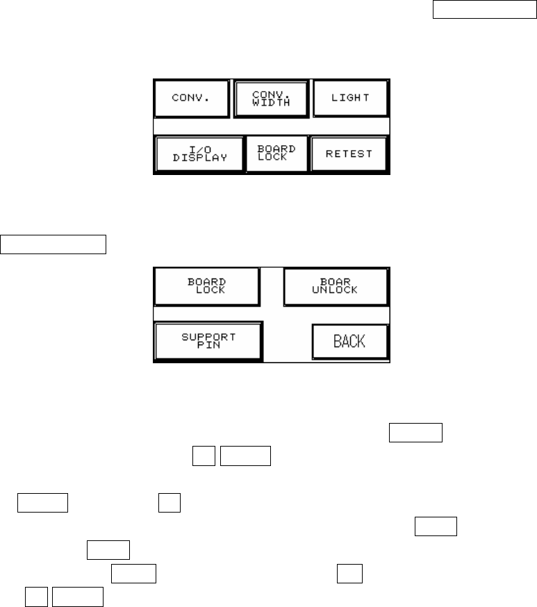
1. Press on the top and left corner of the HCI to enter Figure 2.1, press BOARD LOCK to enter
Figure 2.2.
Figure 2.1
2. Press SUPPORT PIN setting to enter Figure 2.3.
Figure 2.2
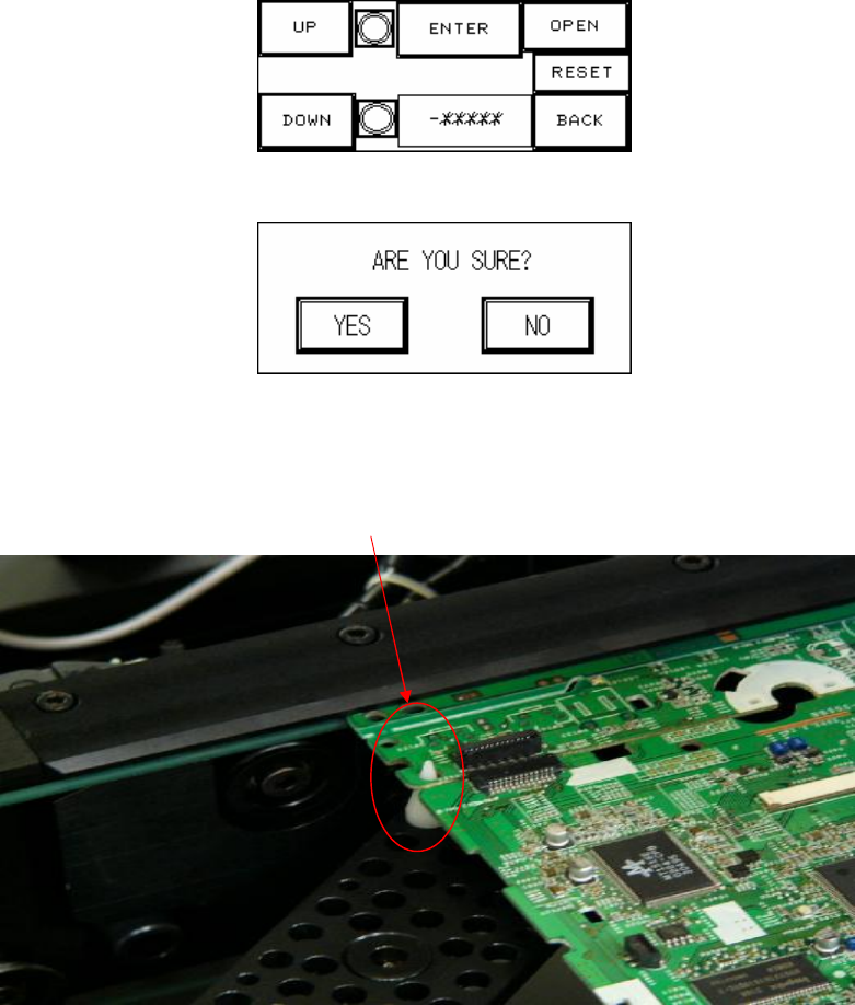
3. Place the candidate board at the loading Sensor and press ENTER. Wait until the Support
Pin is in position then press the UP/DOWN button to gradually adjust it up and down. First it
needs to be moved to the lowest position (the lower limit indicator light will be lit) and then
press RESET. Now press UP to adjust it to the location to support the candidate board as
shown in Figure 2.5 below. The setting value will be shown at -******, and when setting is
complete press BACK. If this accessory was not purchased or is not in use, please make
sure that you press OPEN and at Figure 2.4 choose NO (or it can not be reset). To the right
of the UP/DOWN buttons are their respective upper and lower elevation limit Sensor
33
indicator lights. If the indicator light is lit, it means the limit has been reached.
Figure 2.3
Figure 2.4
Figure 2.5
The point the SUPPORT PIN needs to support.
34
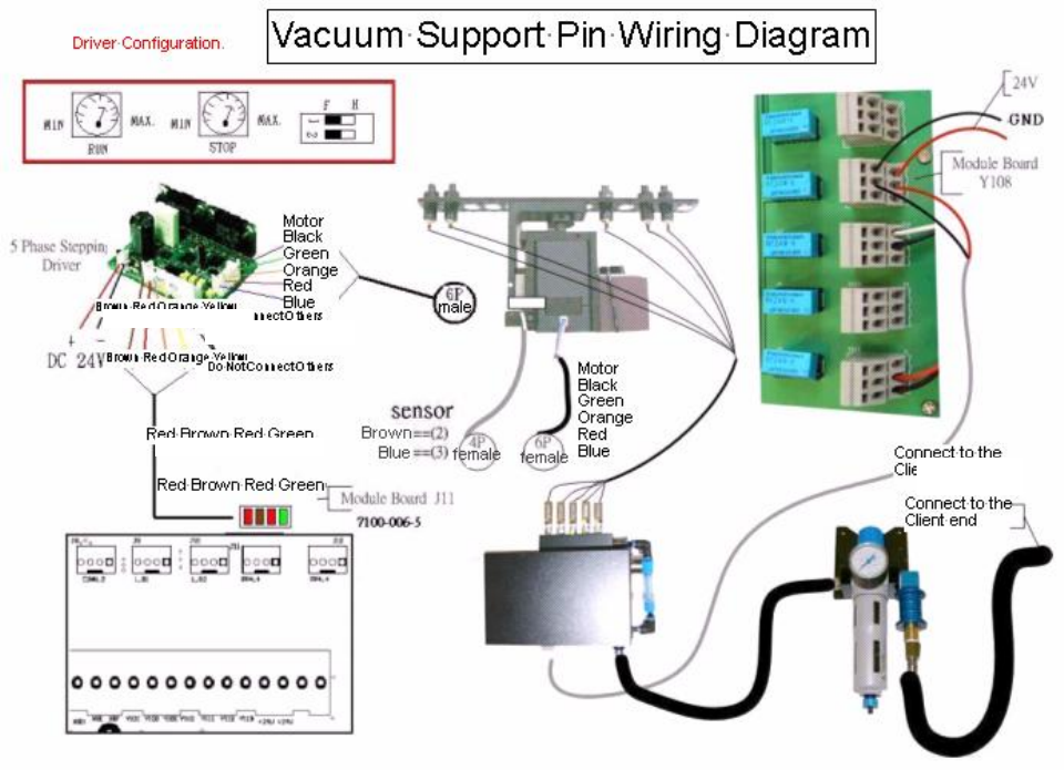
3.4 Wiring Diagram
Brown Red Orange Yellow
Do Not Connect Others
Connect to the
Client end
Red Brown Red Green