TR7500_Hardware_en - 第51页
50 5 A u t o ma t i c C on v e y o r W i d t h A d j u s t m e n t 5 . 1 A r c h i t ect u r e a n d F u n ct io n l T h e A u to m a t i c C o n v e y o r W i dt h A d j u s t m e n t f u n c t i o n a l l o w s t h e c…
49
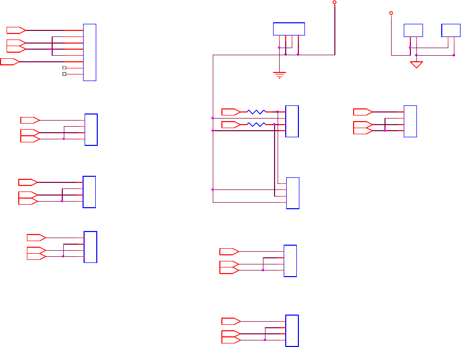
4.2.8 Conveyor & Motor & Signal Tower
Y2A3
X2A3
Front conveyor
DIR(-)_white
J18
TER2
1
2
X1B13
DIR(-)_yellow
J15
MOLEX4
1
2
3
4
Board with
control
PLS(+)_brown
PLS(-)_blue
PLS(+)_brown
X1B4
A_W_OFF
J11
MOLEXSIP4
1
2
3
4
J63
MOLEXSIP4
1
2
3
4
J41
MOLEX2
1
2
SUPORT PIN
A_W_OFF
X1A12
X1B3
Y2B12
Y1B12Y1B3
PLS(-)_red
PLS(-)_red
PLS(-)_red
PLS(-)_red
DIR(-)_yellow
X2B4
DIR(-)_yellow
Left conveyor
PLS(+)_brown
DIR(+)_orange
J64
MOLEXSIP4
1
2
3
4
Y1A12
J62
MOLEXSIP4
1
2
3
4
PLS(-)_red
Y2B13
PLS(+)_brown
J8
MOLEXSIP4
1
2
3
4
X2B12
DIR(-)_yellow
X1B12
Y2B4
DIR(+)_orange
Y2B3
Up-Holder
Up-Holder
X2B13
J9
MOLEXSIP4
1
2
3
4
PLS(-)_red
Up-Holder
+5V
R341.2K
X2B3
Right conveyor
DIR(+)_yellow
Y2A12
Spare
+24V
X2A12
PLS(+)_red
Up-Holder
DIR(+)_orange
J61
MOLEXSIP8
1
2
3
4
5
6
7
8
DIR(-)_yellow
Y1B13
Y1A3
R332.4K
J10
MOLEXSIP4
1
2
3
4
Rear up-holder
- + - +
DIR(+)_orange
PLS(+)_brown
DIR(+)_orange
Front up-holder
PLS(+)_brown
X1A3
J7
MOLEXSIP4
1
2
3
4
Rear conveyor
DIR(+)_orange
DIR(-)_yellow

50
5 Automatic Conveyor Width Adjustment
5.1 Architecture and Function
l The Automatic Conveyor Width Adjustment function allows the conveyor width to be
adjusted directly through the HCI buttons. During programming the conveyor width
adjustment results can be recorded in the main program, so the next time the program is
launched it will automatically adjust the conveyor width to the previously stored location.
l Motor Driver Dip Switch jumps to point 1 and 2.
5.2 Automatic Conveyor Width Settings
l For configuring the PLC please refer to 1.2-1.3.1.
51
6 Service
6.1 PC/PLC Connecting
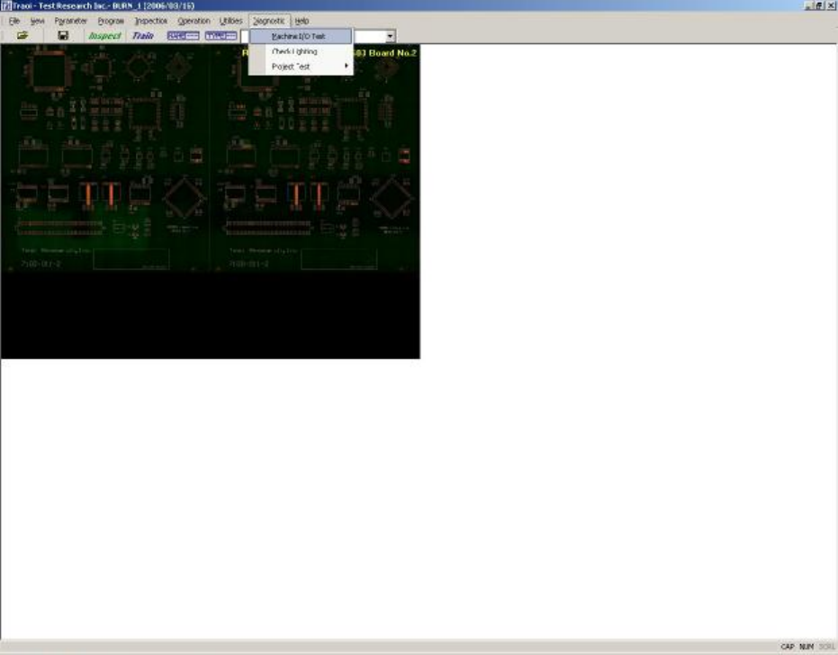
l First confirm that the main program has begun testing. If not running, please start the
program and repeat a test of the PLC. If there is still a problem, please launch the main
program and the PLC I/O TEST to test the system manually to see if the I/O is operating
normally (the settings and procedure are as the figures below). If there is still no response,
please carry out Step 2 and Step 3 to examine the wiring and system. If manual testing
shows that everything is normal, check the program version or contact support personnel for
assistance.
6.1.1 Opening the PC I/O Testing Display