TR7500_Hardware_en - 第62页
61 P r o b l e m C a u s e S o l u t i on M o t o r d o e s no t w o r k a t a ll 1 . Mo t o r m a l f u n c t i on 2 . W i r i n g p r o b l e m 1 . R ep l a c e m o t o r 2 . C h e c k t o s ee i f w i r i ng * 1 i s m…
60
6.4 Holder Motor
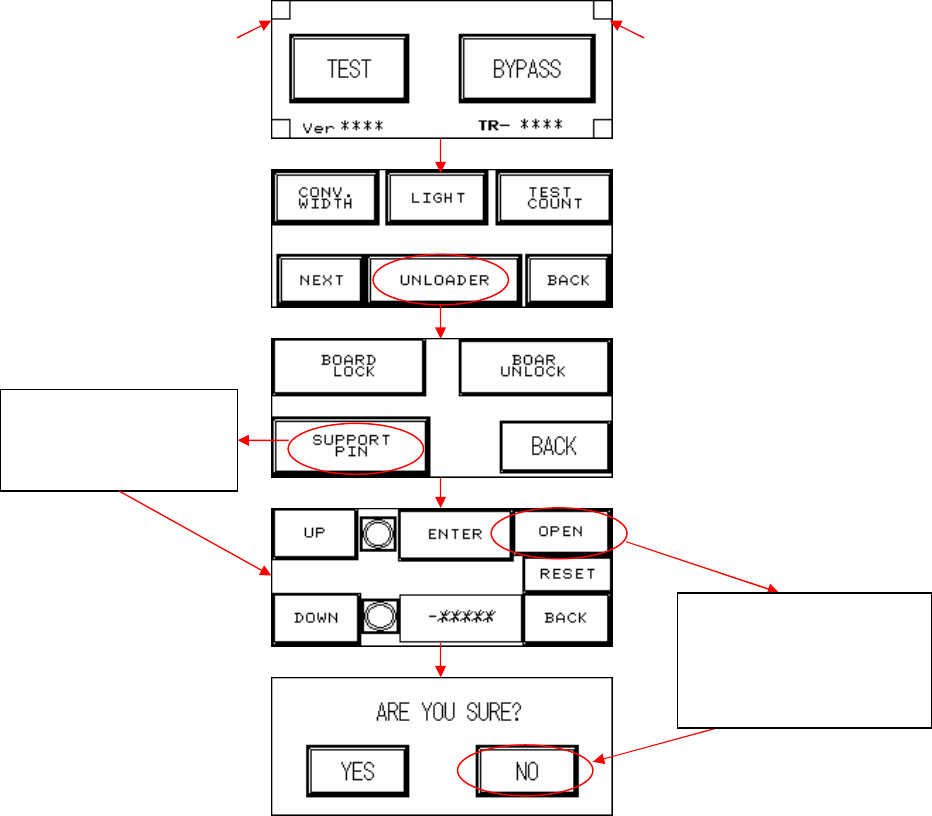
l Elevation Motor Not in Position: First perform a test manually (press the two hidden buttons
simultaneously, the configuration procedure is as figure below) to check if it’s a problem with
the holder motor or with the support motor (if support device is not installed, please do not
activate this option. If accidentally pressed please select NO). Observe the results and refer
to the following table to troubleshoot.
If Suppor
t device
does not operate,
press here to test or
re
-
test
Hidden button Hidden button
If no Support device
fitted, do not press
OPEN. If accidentally
pressed, please select
NO.
61
Problem Cause Solution
Motor does not work at all
1. Motor malfunction
2. Wiring problem
1. Replace motor
2. Check to see if wiring *1 is
malfunctioning or detached.
Current in Motor, but
Does Not Run
1. Mechanical obstruction
2. Incorrect driver setting
1. Remove obstruction
2. Check current and switch
settings.
Motor reaches end limit
but does not stop
1. Incorrect limit sensor
position
2. Limit sensor malfunction
1. Check installation position of
sensor
2. Replace sensor
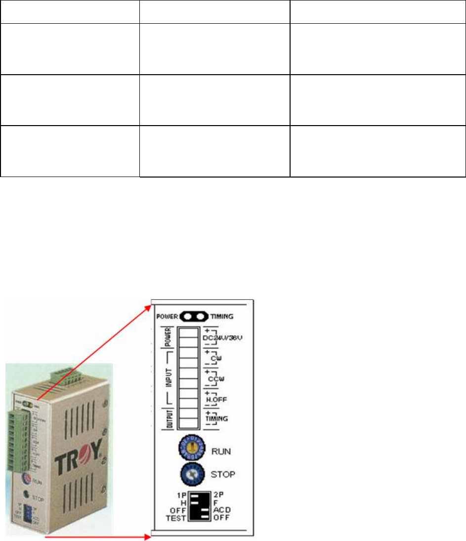
6.4.1 Check Stepping Motor Driver Problem
l Are the RUN & STOP currents set to 80% and the switch positions as below? If not, please
configure them using the procedure below:
l There are two variable resistors located below the Driver. There’s a cross-shaped location
where the variable resistor can be adjusted. Use the adjustment rod to turn the arrow at the
cross location, turn in the clockwise direction to increase.
6.4.2 Replacement:
l Driver: First turn off the power then remove the two sets of wires and two DC +24V power
supply cables from the Driver. There’s a screw at the top and bottom of the driver, remove
the screws to install the new Driver. Once replacement is complete, reconnect the wiring
and power cables. After replacement re-adjust the driver using the adjustment method.
62
l Holder Motor: Unfasten the four screws on the top of the motor and remove the cover.
Unfasten the screw securing the spring inside the cover and remove the spring. Now
unfasten the four screws around the motor and detach the wire connected to the machine.
The motor can now be removed.
6.5 INLINE
l INLINE PORT: First check to see if it’s the front or back stage that has the problem.
6.5.1 Does Not Load
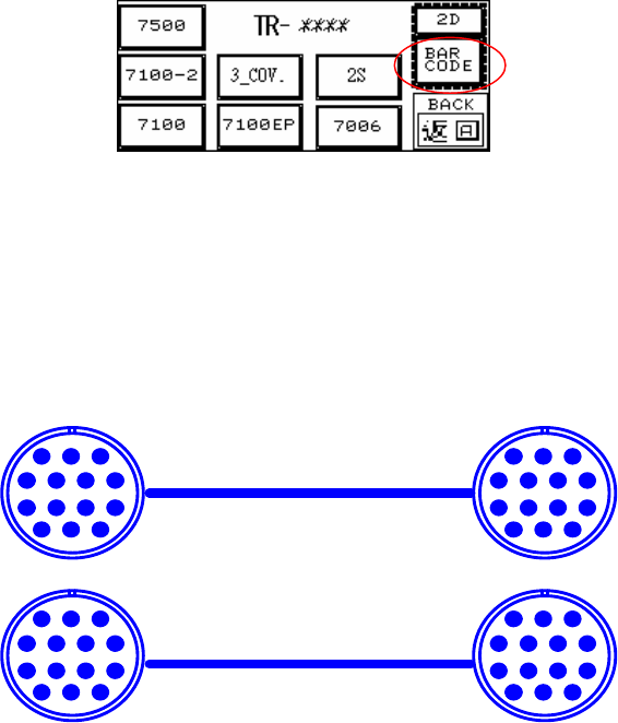
l LOADER: First highlight the BAR CODE, and if board can now be loaded that means there’s
a problem with the Barcode settings in the main program. If board still can’t be loaded this
indicates a problem with the wiring.
l Inspect the Barcode Setting-Barcode Button (Disable/Enable): Highlight so the main
program will not examine the barcode (don’t wait for signal from main program on PC for
loading); Clear the highlight if it is to be examined (wait for signal from main program on PC
for before loading). This option works the same way for 1D or 2D Barcode settings.
l Check that the Loader Wiring is Correct (As Figure Below)
6.5.2 Does Not Unload Unloader
l Unloader Not Ready
l Check that the Unloader Wiring is Correct (As Figure Below):
6.5.3 Signal Meaning
PIN1~PIN6
123
4567
891011
121314
PIN1~PIN6
123
4567
891011
121314
123
4567
891011
121314
123
4567
891011
121314