ET8383-說明書(英文) - 第14页
10 5-pin s ocket Pin NO. Pin’s nam e Instruction of pins Remark 1 24V DC Power supply “+” 2 0V Pow er supply “-” 3 Ein9 X Axis X Axis home sens or signal 4 Ein10 Y Axis Y Axis home sensor signa l 5 Eout9 Enable Enable ca…
9
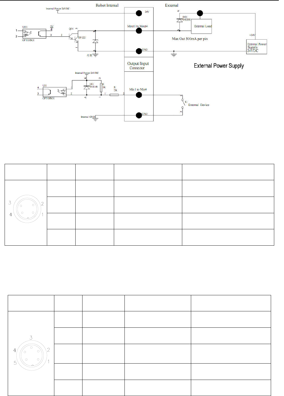
3.2.2 Four-pin Socket Instruction
The fol
lowing list describes the function of 4-pin socket, it is connected to key box.
4-pin socket Pin NO.
Pin’s name
Instruction of pins Remark
1
Min4
Mai
n inputting 4 signal
It’s used to connect to “start/pause”
button.
2
GND
Powe
r supply “-” Power supply “-”
3
Min1
Main inputting 1 signal It is used to reset (ORG) signal
4
EMST
Em
ergency stop button
It is used to emergency stop
button.
N
OTE: * If the customers need special function, the input and output signal can be set again.
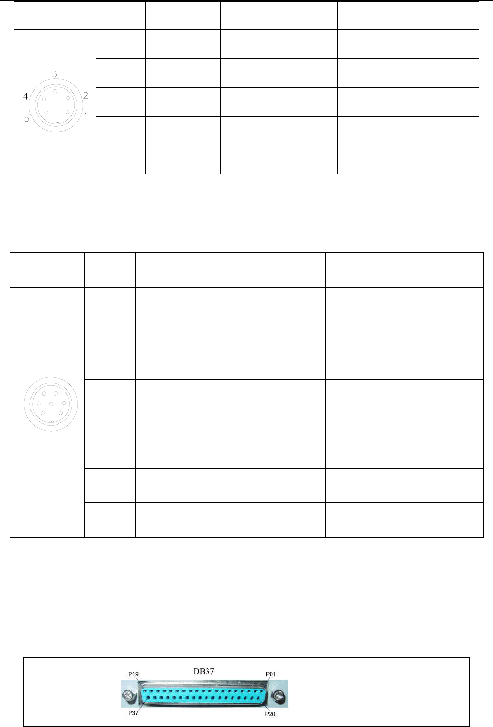
3.2.3 Five-pin Socket Instruction
The following list describes the function of 5-pin socket, it is a spare socket.
5-pin socket Pin NO.
Pin’s
name Instruction of pins Remark
1 24V
DC “+” power supply
2 G
ND Power supply “-”
3 Mi
n3 Main inputting 3 signal
Safety signal ,such as safety
light curtain \safety door etc.
4 Ein13 Exter
nal input 13 signal
5 Ein14 External input 14 signal
The following list describes the function of 5-pin socket, it’s used to light house.
10
5-pin s
ocket Pin NO.
Pin’s nam
e Instruction of pins Remark
1 24V
DC Power supply“+”
2 0V Pow
er supply“-”
3 Ein9 X
Axis X Axis home sensor signal
4 Ein10 Y
Axis Y Axis home sensor signal
5
Eout9
Enable
Enable ca
libration signal
N
OTE: * If the customers need special function, the input and output signal can be set again.
3.2.4 Seven-pin Socket Instruction
The fol
lowing list describes the pins function of the seven-pin socket. It is connected to dispensing controller.
7-pin socket Pin NO.
Pin’s nam
e Instruction of pins Remark
1
2
3
4
5
6
7
1 24V
DC Power supply“+”
2 0V Pow
er supply“-”
3 Mout1
Main signal output1, the
current is less than 0.5A
It’s used to feeding signal.
4 Mout
4
Main signal output4, the
current is less than 0.5A
It
’s used to cylinder movement
signal.
5 Ein12 Exter
nal input 12 signal
It’s used to reset (ORG) signal,
alarm when solder wire is
blocking or lacking etc.
6 Mout
2
Main signal output2, the
current is less than 0.5A
It
’s used to output working state
signal.
7 Mout
5
Main signal output5, the
current is less than 0.5A
I
t’s only effective as pulse signal
inputted.
N
OTE: * If the customers need special function, the input and output signal can be set again.
3
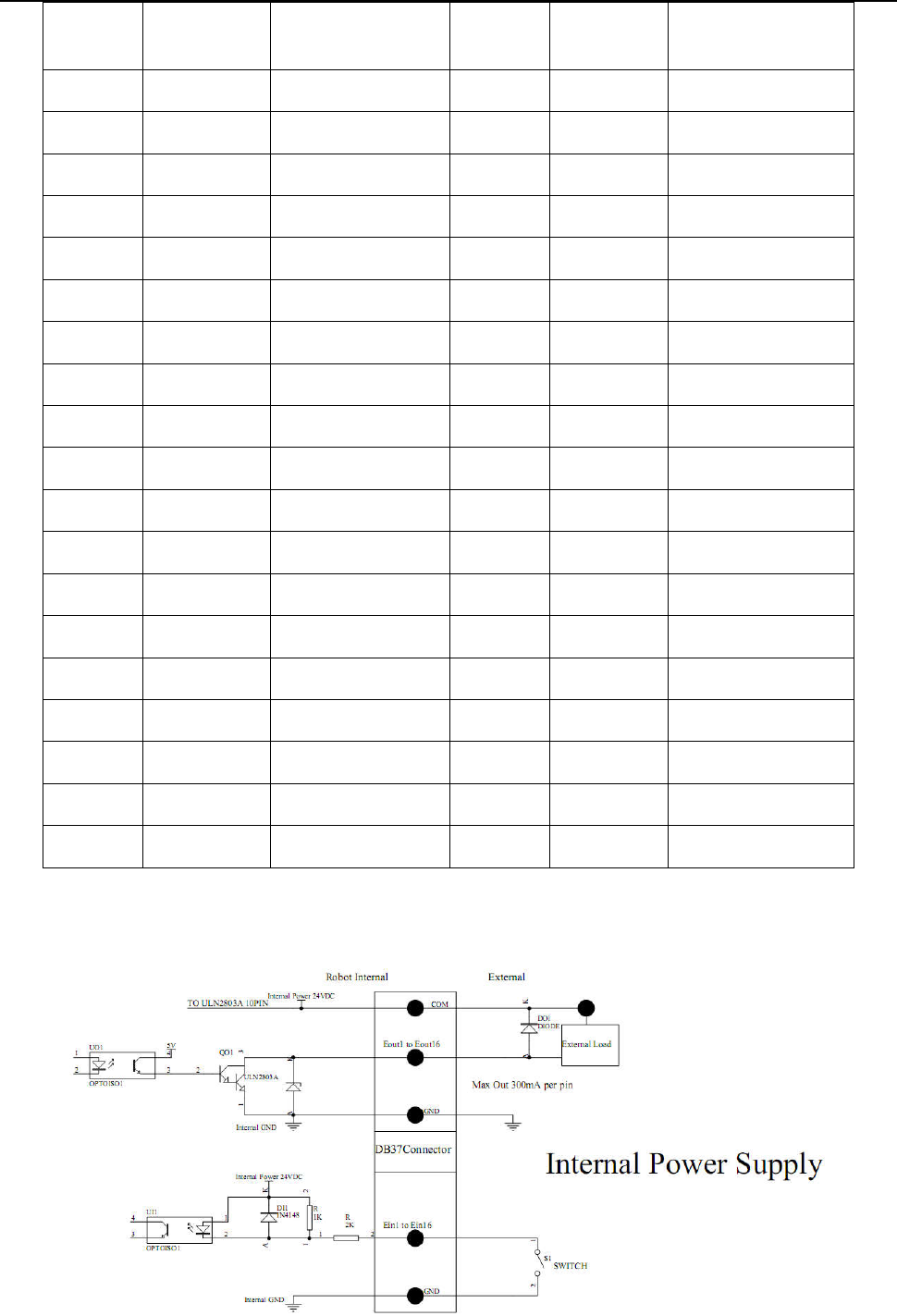
.3 Instruction about DB37 socket
NOT
E: DB37 socket is an optional fitting. It must be ordered if you need it to do information input or output.
3.3.1 Pins Instruction of DB37
(s
ocket of DB37)
11
NO.
De
finition of
DB37 pins
Corresponding I/O
interface of DB37
NO.
Definition
of DB37
pins
Corresponding I/O
interface of DB37
1 G
ND P01 20 GND P20
2 Eout8 P02 21 Ein8 P21
3 Eout7 P03 22 Ein7 P22
4 Eout6 P04 23 Ein6 P23
5 Eout5 P05 24 Ein5 P24
6 Eout4 P06 25 Ein4 P25
7 Eout3 P07 26 Ein3 P26
8 Eout2 P08 27 Ein2 P27
9 Eout1 P09 28 Ein1 P28
10 COM P10 29 G
ND P29
11 G
ND P11 30 Ein16 P30
12 Eout16 P12 31 Ein15 P31
13 Eout15 P13 32 Ein14 P32
14 Eout14 P14 33 Ein13 P33
15 Eout13 P15 34 Ein12 P34
16 Eout12 P16 35 Ein11 P35
17 Eout11 P17 36 Ein10 P36
18 Eout10 P18 37 Ein9 P37
19 Eout9 P19
3.3.2 Circuit Instruction of DB37