ET8383-說明書(英文) - 第21页
17 Eout3 - -, Nozzle 1, Noz zle 2, Nozzle 3, Nozzle 4 Eout4 - -, Nozzle 1, Noz zle 2, Nozzle 3, Nozzle 4 Eout5 - -, Nozzle 1, Noz zle 2, Nozzle 3, Nozzle 4 Eout6 - -, Nozzle 1, Noz zle 2, Nozzle 3, Nozzle 4 Eout7 - -, No…

16
Ein15
--, Origin BTN, Stop BTN, Start BTN, Foot BTN, Safe flag-1, Safe flag-2,
Shortcut 266, Lack fault, Block fault, Temp fault, Temp\Feed fault, Upper
CS, Nether CS, Pressure flag
Ein16
--, Origin BTN, Stop BTN, Start BTN, Foot BTN, Safe flag-1, Safe flag-2,
Shortcut 267, Lack fault, Block fault, Temp fault, Temp\Feed fault, Upper
CS, Nether CS, Pressure flag
K
in1
--、Upper CS, Nether CS
K
in2
--、Upper CS, Nether CS
Kin3
--、Upper CS, Nether CS
K
in4
--、Upper CS, Nether CS
2. I
n the “Output Config 2” display window, the input interface can be set:
Out
put Port
Optiona
l Function
Mout
1
-
-, Nozzle 1, Nozzle 2, Nozzle 3, Nozzle 4, Working Flag, Work End
Flag, Cylinder, Clean Output
Mout
2
-
-, Nozzle 1, Nozzle 2, Nozzle 3, Nozzle 4, Working Flag, Work End
Flag, Cylinder, Clean Output
Mout
3
--, Nozzle 1, Nozzle 2, Nozzle 3, Nozzle 4, Working Flag, Work End
Flag, Cylinder, Clean Output
Mout
4
-
-, Nozzle 1, Nozzle 2, Nozzle 3, Nozzle 4, Working Flag, Work End
Flag, Cylinder, Clean Output
Mout
5
-
-, Nozzle 1, Nozzle 2, Nozzle 3, Nozzle 4, Working Flag, Work End
Flag, Cylinder, Clean Output
Mout6
--, Nozzle 1, Nozzle 2, Nozzle 3, Nozzle 4, Working Flag, Work End
Flag, Cylinder, Clean Output
Mout
7
-
-, Nozzle 1, Nozzle 2, Nozzle 3, Nozzle 4, Working Flag, Work End
Flag, Cylinder, Clean Output
Mout
8
-
-, Nozzle 1, Nozzle 2, Nozzle 3, Nozzle 4, Working Flag, Work End
Flag, Cylinder, Clean Output
Eout1
-
-, Nozzle 1, Nozzle 2, Nozzle 3, Nozzle 4
Eout2
-
-, Nozzle 1, Nozzle 2, Nozzle 3, Nozzle 4

17
Eout3
-
-, Nozzle 1, Nozzle 2, Nozzle 3, Nozzle 4
Eout4
-
-, Nozzle 1, Nozzle 2, Nozzle 3, Nozzle 4
Eout5
-
-, Nozzle 1, Nozzle 2, Nozzle 3, Nozzle 4
Eout6
-
-, Nozzle 1, Nozzle 2, Nozzle 3, Nozzle 4
Eout7
-
-, Nozzle 1, Nozzle 2, Nozzle 3, Nozzle 4
Eout8
-
-, Nozzle 1, Nozzle 2, Nozzle 3, Nozzle 4
Eout9
-
-, Ready Flag, Alarm Flag, Working Flag, Work End Flag, Cylinder,
Clean Output, Pause Output, Left LED, Right LED, Emer Output,
Eout10
-
-, Ready Flag, Alarm Flag, Working Flag, Work End Flag, Cylinder,
Clean Output, Pause Output, Left LED, Right LED, Emer Output,
Reset Output, EnNozzleAdj
Eout1
1
-
-, Ready Flag, Alarm Flag, Working Flag, Work End Flag, Cylinder,
Clean Output, Pause Output, Left LED, Right LED, Emer Output,
Reset Output, EnNozzleAdj
Eout12
-
-, Ready Flag, Alarm Flag, Working Flag, Work End Flag, Cylinder,
Clean Output, Pause Output, Left LED, Right LED, Emer Output,
Reset Output, EnNozzleAdj
Eout13
-
-, Ready Flag, Alarm Flag, Working Flag, Work End Flag, Cylinder,
Clean Output, Pause Output, Left LED, Right LED, Emer Output,
Reset Output, EnNozzleAdj
Eout14
-
-, Ready Flag, Alarm Flag, Working Flag, Work End Flag, Cylinder,
Clean Output, Pause Output, Left LED, Right LED, Emer Output,
Reset Output, EnNozzleAdj
Eout15
-
-, Ready Flag, Alarm Flag, Working Flag, Work End Flag, Cylinder,
Clean Output, Pause Output, Left LED, Right LED, Emer Output,
Reset Output, EnNozzleAdj
Eout16
-
-, Ready Flag, Alarm Flag, Working Flag, Work End Flag, Cylinder,
Clean Output, Pause Output, Left LED, Right LED, Emer Output,
Reset Output, EnNozzleAdj
3.I
n the teaching pendant, “Eout09~Eout16” are corresponding to the “Eout8+ (0~8)” at the “I
O
T
est” and “Output (point)” displaying window.
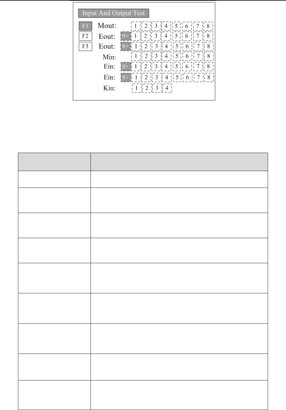
18
Nam
ely, “Eout8+ 1” is the output interface “Eou09”. “Eout8+ 2” is the output interface “Eou10”.
“Eout8+ 3” is the output interface “Eou11”, etc.
3.5.2 IO Function Instruction
Input si
gnal function
Functio
n Instruction
-- N/A.
Origi
n BTN
Input the reset signal into the unit by corresponding signal pin, and
the unit will run the reset (ORG) operation.
S
top BTN
Input the stop signal into the unit by corresponding signal pin, and
the unit stops the current operation.
S
tart BTN
Input the start signal into the unit by corresponding signal pin, and
the unit starts to work or pauses the current work.
F
oot BTN
Input the foot switch signal into the unit by corresponding signal pin
and the unit runs the foot switch operation and the function is
similar with the “Start BTN”.
Safe f
lag-1
Input the signal “breakover ground” into the unit by corresponding
signal pin and the unit comes into the testing state (cannot move and
can only be programmed).
Safe f
lag-2
Input the signal “break over ground” into the unit by corresponding
signal pin and the unit comes into the testing state (cannot move and
can only be programmed).
L
ack fault
Input the signal “lack fault” into the unit by corresponding signal pin
and the unit comes into the process, such as stop working, alarming
et
c..
Block f
ault
Input the signal “block fault” into the unit by corresponding signal
pin and the unit comes into the process, such as stop working,
alarming etc..