CM602all_EJM8AESM_Service Manual.pdf - 第1002页
(1) Select the tray. (2) Jig setting Put Nozzle 1003 on Head 3. (3) Height teach (4) Position teach (5) Jig remove Remove the Nozzle 1003 from Head 3. Installation is finished. Adjust the feeder-reel-support height if ne…
AR connection
• Channel setting CHSW = 0
• Mode setting MODESW = 5
BR connection (Same as AR)
• Channel setting CHSW = 0
• Mode setting MODESW = 5
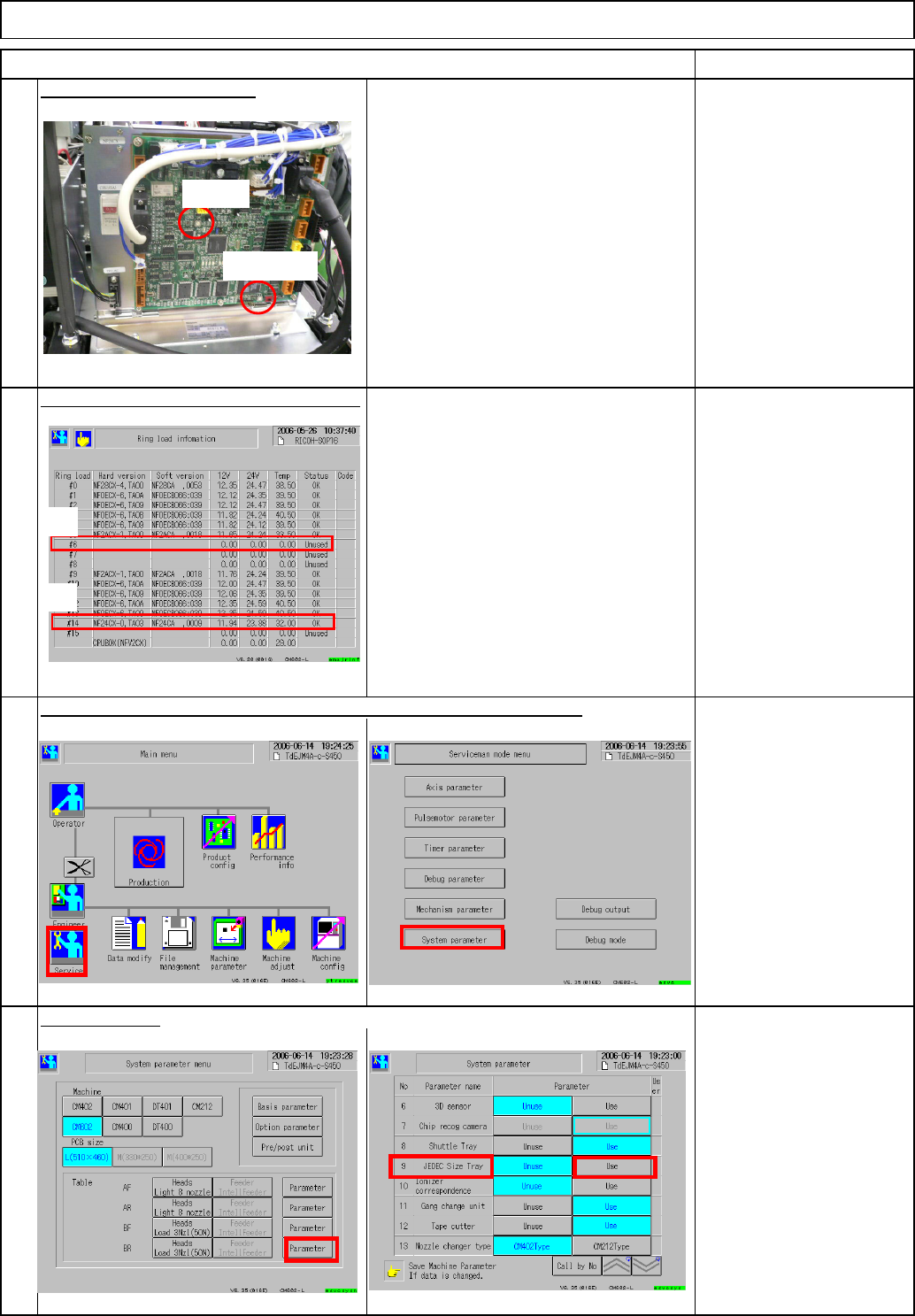
AR: Ring load #6
BR: Ring load #14
Key disk
Select the tray.
No problems as long as the version is
displayed on the Ring load information
screen.
Tray Direct Tray
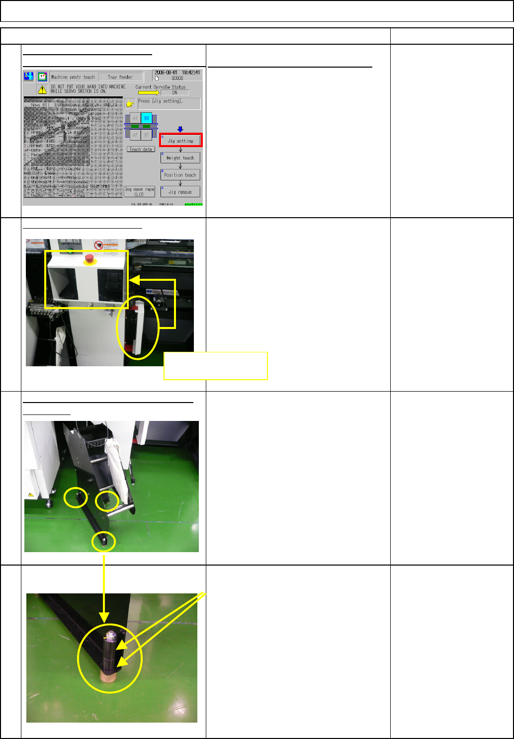
Check the setting of NF24CX on the
front of the box.
19
Check the direct tray is set to "Use," checking the system parameter.
18
Check communication with the machine.
20
RemarkItem
Check the NF24CX setting.
17
CHSW
MODESW
AR
BR
EJM8A-E-SMA070201-A01-00
Page 7-2-1-6
(1) Select the tray.
(2) Jig setting
Put Nozzle 1003 on Head 3.
(3) Height teach
(4) Position teach
(5) Jig remove
Remove the Nozzle 1003 from Head 3.
Installation is finished.
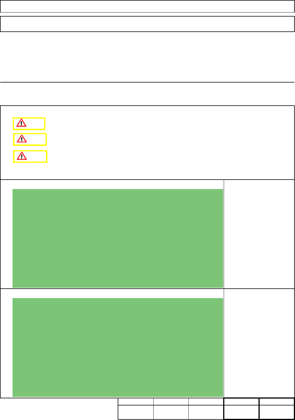
Adjust the feeder-reel-support height if
necessary. When adjusting the tape-feeder-reel-
support height, adjust the height with the
three positions shown at left.
To adjust the height, use these two
collars. Insert the collar between the
plate and the adjusting bolt, and adjust
the height.
Tray Direct Tray
Item
Nozzle 1003
Remark
23
21
Install the machine covers.
Teach (in Serviceman mode)
Machine parameter/Machine parameter teach
See 7-2-2. Pickup Position Teaching.
22
24
Remove the cover from the side shown
at left, and put it on the front.
Remove the cover,
and put it on the front.
EJM8A-E-SMA070201-A01-00
Page 7-2-1-7
Tray
kgs.
7
Min.
0
7-2-2 Direct Tray Pickup Position Teaching
Removal/Disassembly
70
Nozzle 1003
Teaching
Min. Min.
Direct Tray
• This section describes the procedures for teaching the direct tray pickup position.
Total Part Weight
Assembly/Adjustment
Tool
Jig
Min.
Caution
Danger
Warning
EJM8A-E-SMA070202-A01-00
Page 7-2-2-1