CM602all_EJM8AESM_Service Manual.pdf - 第1008页
Jig: FM-1924 Level: (0.02mm/div.) Magazine NG palette position, the lowest-level Palette jig FM-1931 lowest-level of the lower magazine. Lock the door guide, pressing it in the direction of the palette jig and . Chec…
Jig: FM-1924
Level: (0.02mm/div.)
Jig: FM-1924
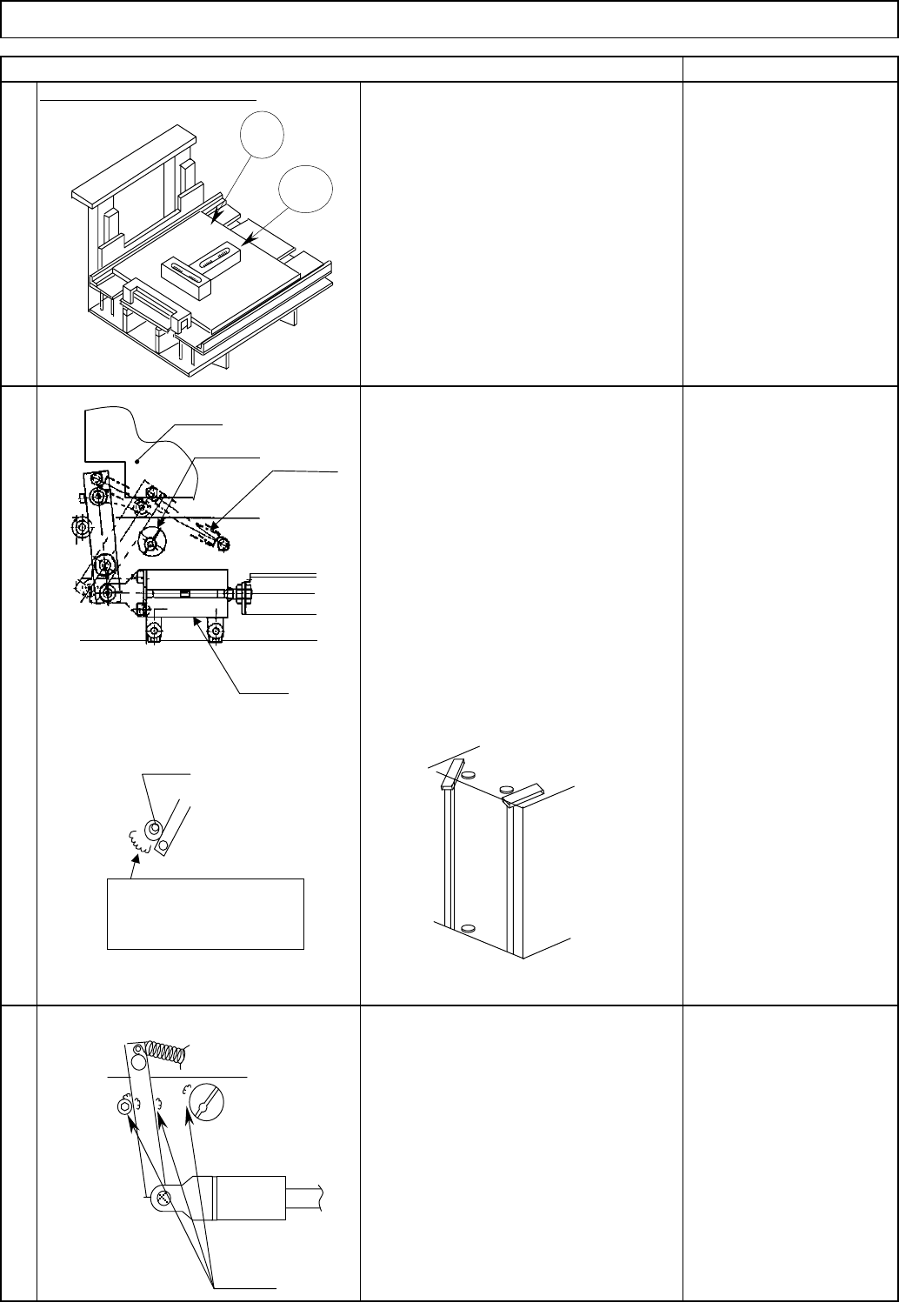
Put the jig on the extension section.
Check at the positions and .
Greasing (MP Grease 2S)
X and Y directions: Within 0.1 mm/m
2
3
Adjust the stopper pin.
Do not let grease go down.
RemarkItem
Level the extension section.
Direct TrayTray
Level the extension section with the jig
and the level.
Lock the stopper so that the shaft makes
a slight contact with the edge of the jig.
* Upper: Adjust at the NG discharge
section.
Lower: Adjust at the origin position.
After adjustment, apply grease to the
specified sections. Apply grease to the
stopper-touching sections. (To prevent
wear.)
1
Jig
Level
Jig: FM-1924
Stoppe
r
Spring
Cylinde
r
The wider side of the
eccentric pin is
positioned on this side.
Bolt
Greasing
EJM8A-E-SMA070203-A01-00
Page 7-2-3-2
Jig: FM-1924
Level: (0.02mm/div.)
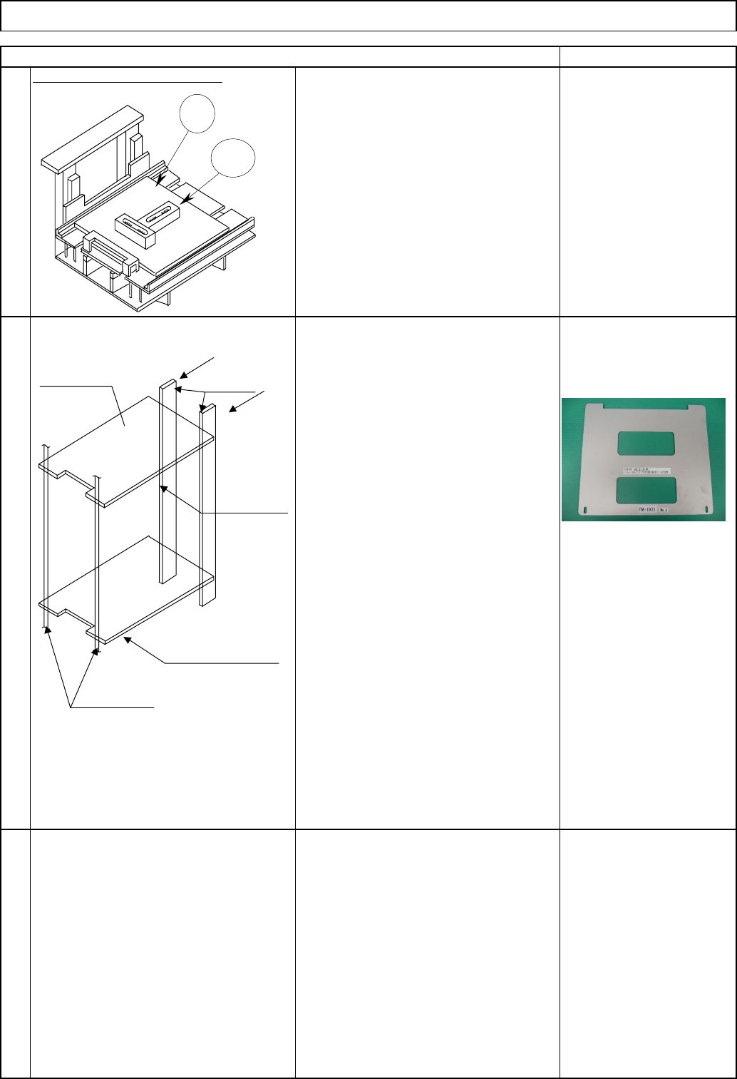
Magazine
NG palette position, the lowest-level
Palette jig FM-1931
lowest-level of the lower magazine.
Lock the door guide, pressing it in the
direction of the palette jig and.
Check there is no gap between the guide
and the palette.
A feeler gauge (T=0.05) should not be
inserted.
Feeler gauge
(T=0.05 mm)
5
Put the magazine on the magazine
holder. Put the palette jig onto the
position of the upper magazine and the
Item
Direct Tray
Remark
4
Supplement: Front door guide
X and Y directions: Within 0.1 mm/m
Level the extension section with the jig
and the level.
Tray
Jig
Level
Palette jig
Door guide
NG palette
position
Lowest-magazine position
of the lower magazine
Magazine shutte
r
EJM8A-E-SMA070203-A01-00
Page 7-2-3-3
Direct Tray
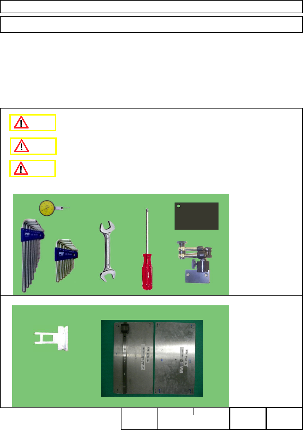
・This section describes the procedures for adjusting the lift-axis stroke.
Total Part Weight
Key switch
FM-1934: Lift-axis height
check jig
Tools
Jigs
Tray
Assembly/Adjustment
7-2-4 Lift-axis Stroke Adjustment
Phillips screwdriver #2
Allen keys 3 - 5 mm
Wrench 14 and 19 mm
Magnetic stand
Dial gauge
Torque wrench
Block gauge 10 mm
35
Min.
Removal/Disassembly
20
Min. Min.
kgs.
Teaching
15
Min.
I Since this adjustment requires releasing the safety cover switch, only those who are authorized
to release it based on the Document "Key Switch/Key Disk Receipt Confirmation and Safety
Precautions" are permitted to perform this adjustment.
Dange
r
Caution
Warning
EJM8A-E-SMA070204-A01-00
Page 7-2-4-1