CM602all_EJM8AESM_Service Manual.pdf - 第1010页
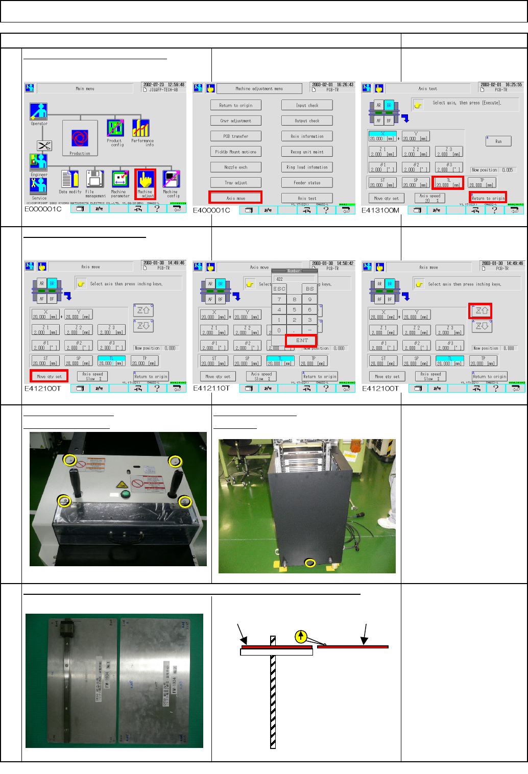
Tray Put the palette jig on the lift table (extension section) and the supply table. Remark Return the lift-axis to the origin. Item 4 Phillips screwdriver #2 M4 screw 4 to 6 pcs. Direct Tray Remove the bolts. Remove the…
Direct Tray
・This section describes the procedures for adjusting the lift-axis stroke.
Total Part Weight
Key switch
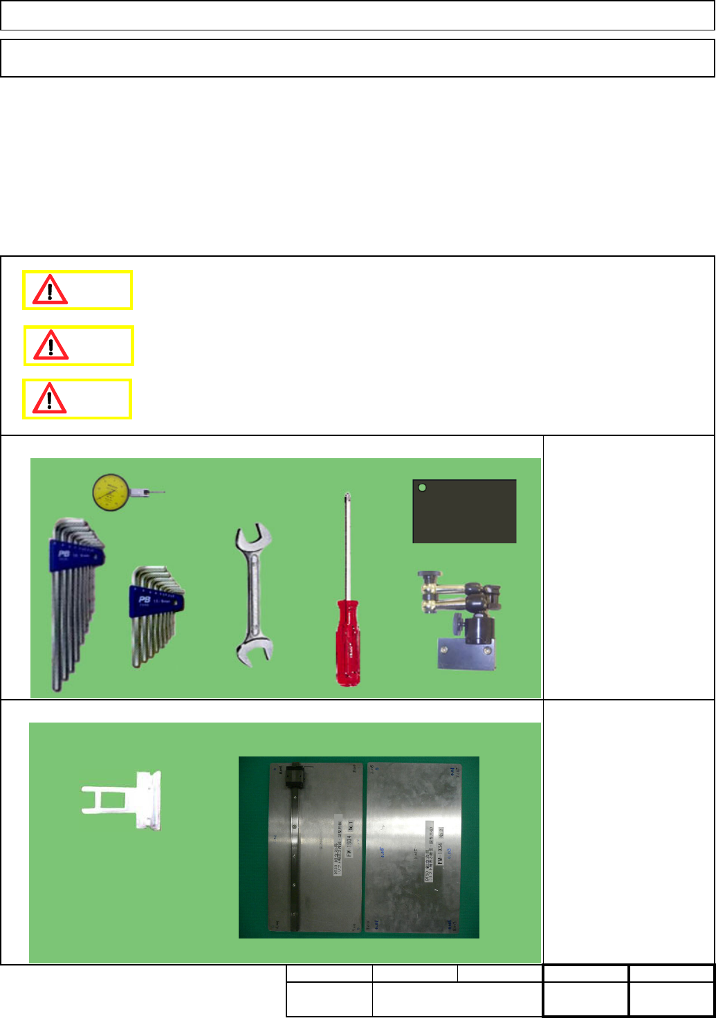
FM-1934: Lift-axis height
check jig
Tools
Jigs
Tray
Assembly/Adjustment
7-2-4 Lift-axis Stroke Adjustment
Phillips screwdriver #2
Allen keys 3 - 5 mm
Wrench 14 and 19 mm
Magnetic stand
Dial gauge
Torque wrench
Block gauge 10 mm
35
Min.
Removal/Disassembly
20
Min. Min.
kgs.
Teaching
15
Min.
I Since this adjustment requires releasing the safety cover switch, only those who are authorized
to release it based on the Document "Key Switch/Key Disk Receipt Confirmation and Safety
Precautions" are permitted to perform this adjustment.
Dange
r
Caution
Warning
EJM8A-E-SMA070204-A01-00
Page 7-2-4-1
Tray
Put the palette jig on the lift table (extension section) and the supply table.
Remark
Return the lift-axis to the origin.
Item
4
Phillips screwdriver #2
M4 screw 4 to 6 pcs.
Direct Tray
Remove the bolts.Remove the cover.
2
1
3
Raise the lift-axis 422 mm.
Jig: FM-1934
Lift-axis height check jig
Turn off the power.
Rear side
422
Lift table
Supply-
section table
Lift-axis ball screw
FM-1934
FM-1934
EJM8A-E-SMA070204-A01-00
Page 7-2-4-2
Tray
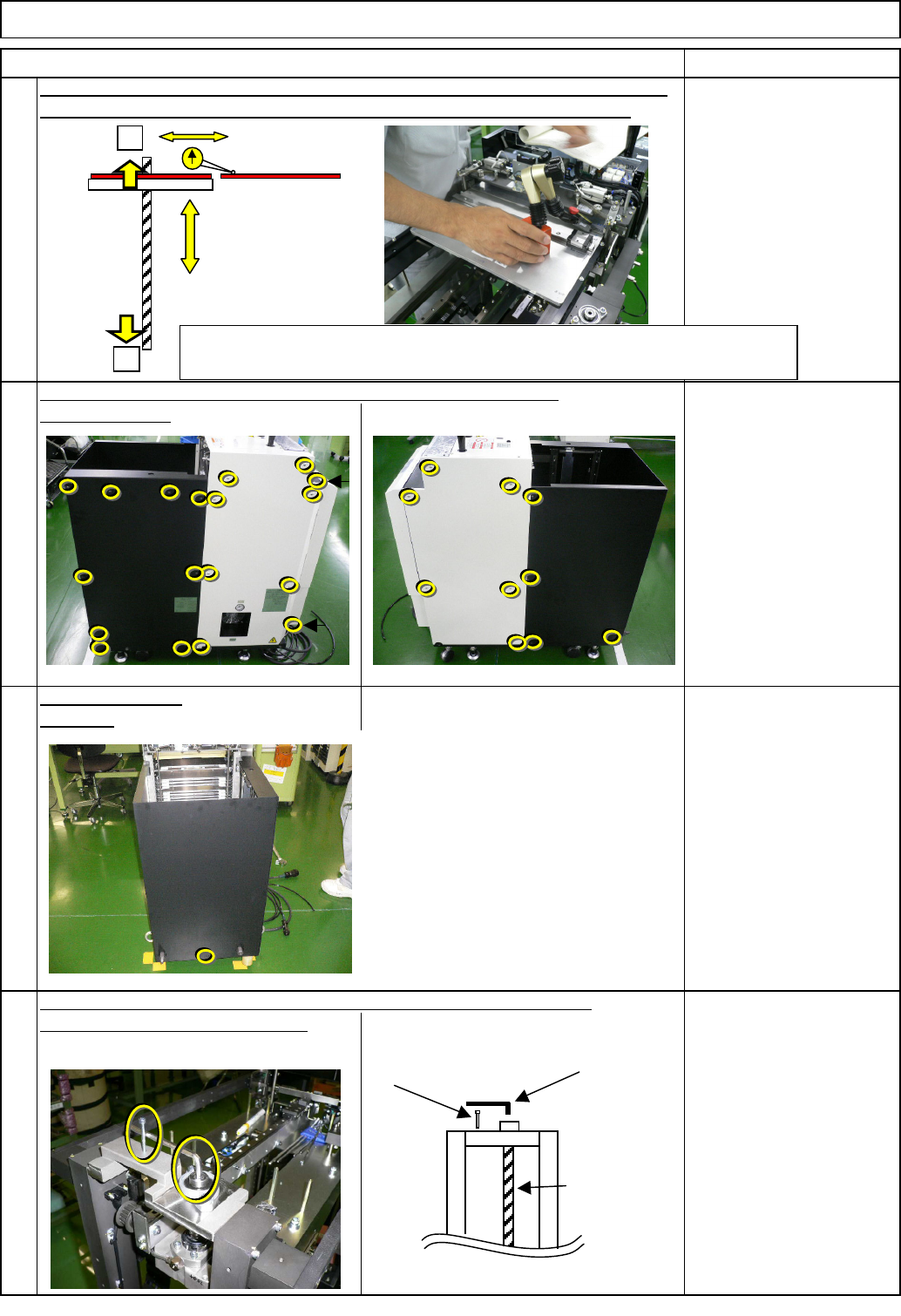
Check the height of the lift table (extension section) and the supply-section table.
Put the magnetic stand and a dial gauge on the lift table (extension section).
Loosening the coupling lowers the lift. To avoid letting the lift descend,
8
6
7
put on an Allen key and the screw.
Item
Rear side
5
Specifications:
within +/-1.0 mm
Magnetic stand
Dial gauge
Remark
Open the cover.
Direct Tray
If outside the +/-1mm, return the lift-axis to the origin (See Step 1).
Remove the bolts.
Phillips screwdriver #2
Screw M4 14 pcs.
Allen key 5 mm
Screw M4 x 40
Allen key 2.5 mm
M3 4 pcs.
Ball screw
Screw M4 x 40
Allen key 5 mm
When inside the range: Offset input and fine-tuning (Go to Step 16)
If outside the range: Adjust the origin position again. (Go to Step 11)
+
-
Spec. within +/-1.0
EJM8A-E-SMA070204-A01-00
Page 7-2-4-3