CM602all_EJM8AESM_Service Manual.pdf - 第1014页
kgs. 30 Direct Tray • This section describes the procedures for replacing the lift-axis driver. Total Part Weight 2 80 7-2-5 Lift-axis Driver Replacement None Phillips screwdriver #2 Precision screwdriver Nippers Allen k…
15
Direct Tray
Item Remark
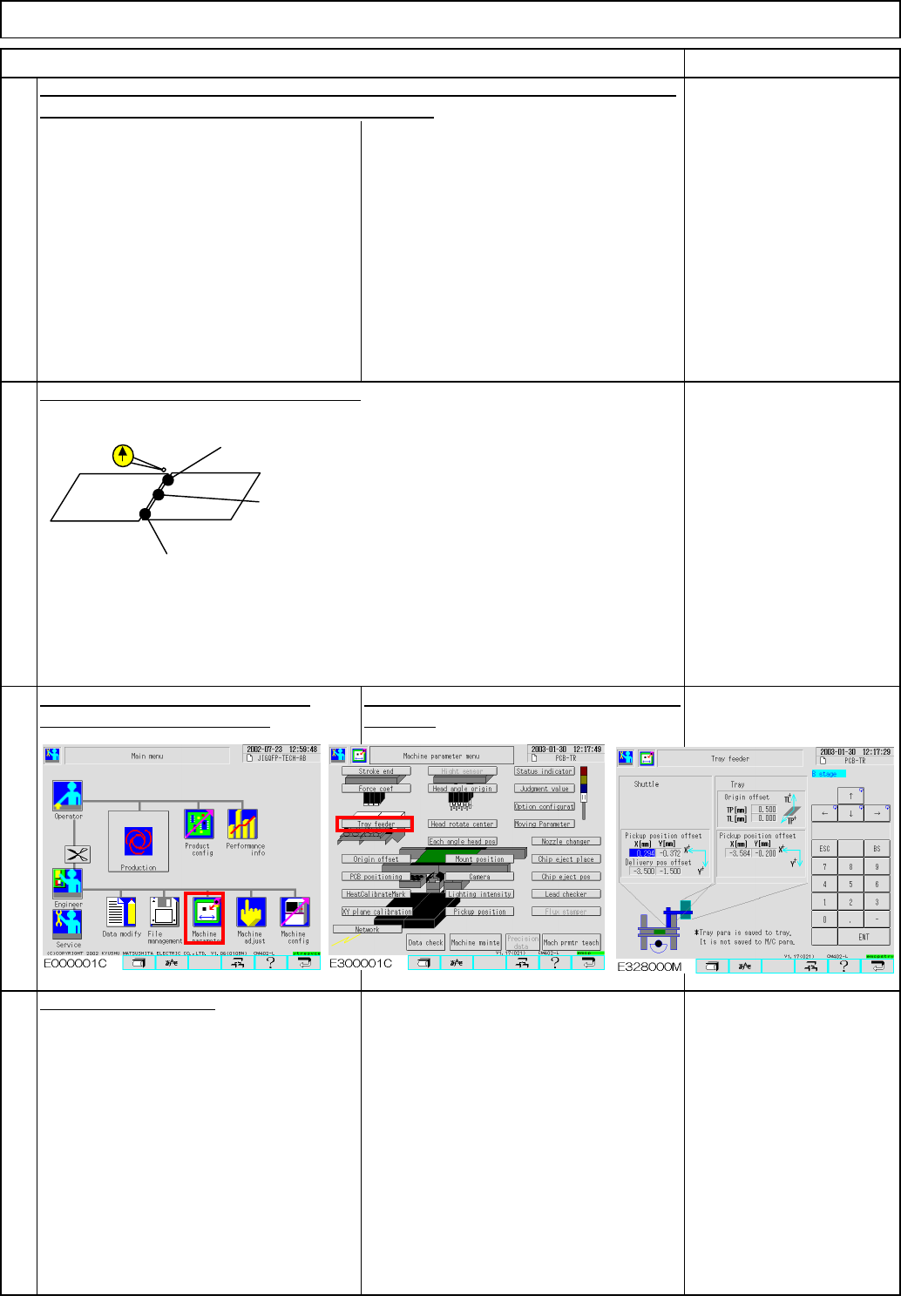
Tray
Enter the measured value into [TL]
manually. Offset = within +/-1
This offset is stored in the tray, not in the
machine.
on to Step 14. If outside the range, repeat Step 11.
14
Check at the three measurement position
13
Repeat Steps 2, 4 and 5. When the step-5 result is within the specifications, move
16
Put the cover back on.
A1 (right and left): within +/- 0.2 mm
A0 (center): within +/-0.05mm
A2(right and left): within +/- 0.2 mm
<B0, B1 and B2 for Stage B>
EJM8A-E-SMA070204-A01-00
Page 7-2-4-5
kgs.
30
Direct Tray
• This section describes the procedures for replacing the lift-axis driver.
Total Part Weight
280
7-2-5 Lift-axis Driver Replacement
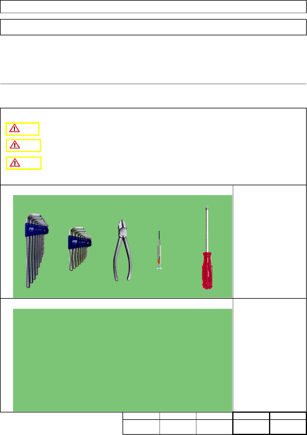
None
Phillips screwdriver #2
Precision screwdriver
Nippers
Allen key M4
Teaching
Assembly/AdjustmentRemoval/Disassembly
30
Min. Min. Min.
20
Tool
Jig
Min.
Tray
Caution
Danger
Warning
EJM8A-E-SMA070205-A01-00
Page 7-2-5-1
4
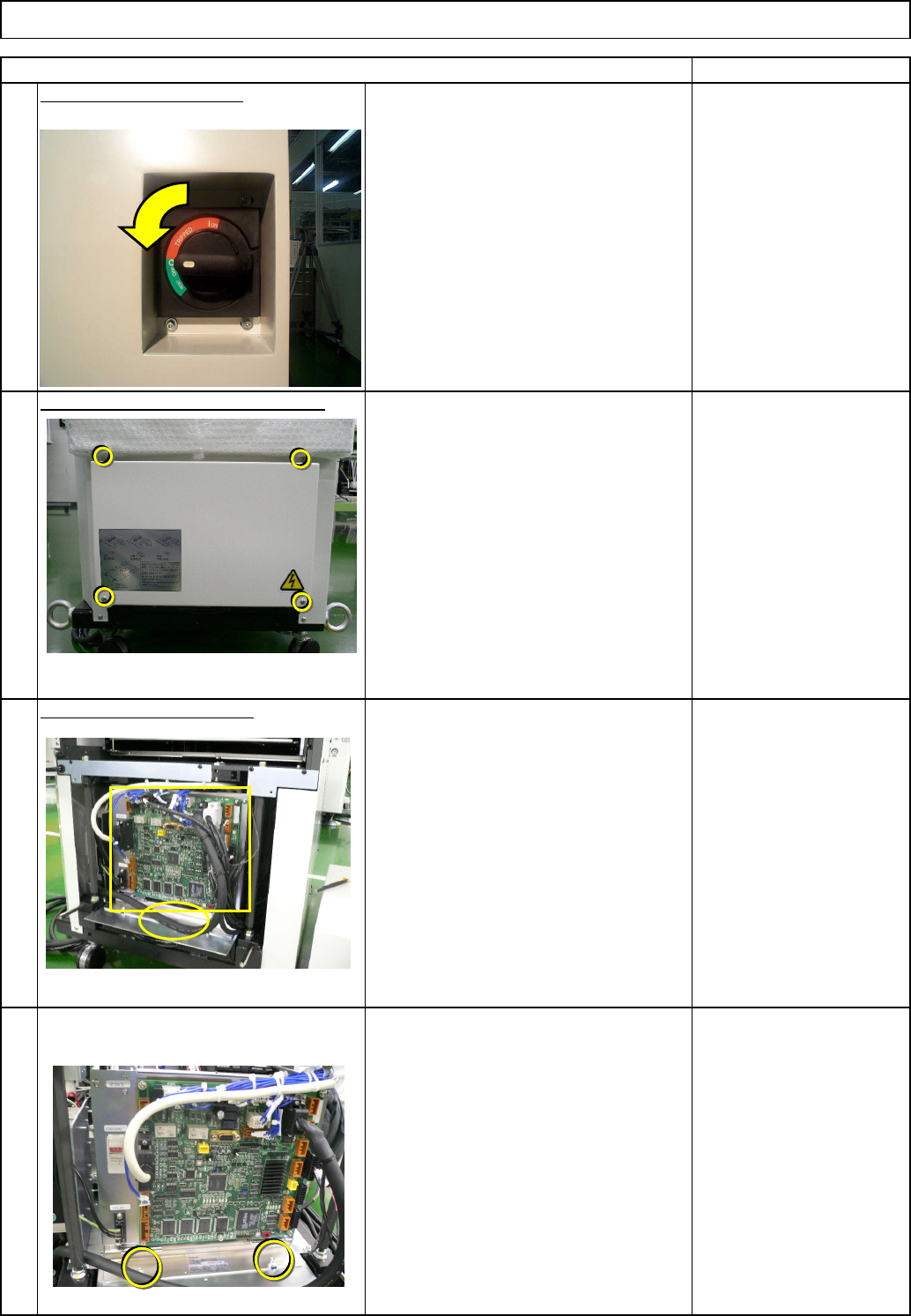
Remove the control-box front cover.
• Remove the box-holding screws.
3
Remove the control-box front cover.
Remark
2
Turn off the power switch.
Remove the lift-axis driver.
• Remove all the connectors from the
front of the control box and from the
board.
• Remove the cable tie from the front of
the control box.
Tray
1
Item
Direct Tray
EJM8A-E-SMA070205-A01-00
Page 7-2-5-2