CM602all_EJM8AESM_Service Manual.pdf - 第1020页
Basic p arameters Name PA01 Control mode 0 0 PA02 Regenerative brake option 0 0 PA03 Absolute position detection system 0 0 PA04 Function selection A-1 1 0 PA05 No. of command input pulses per rotation 0 0 PA06 Electroni…
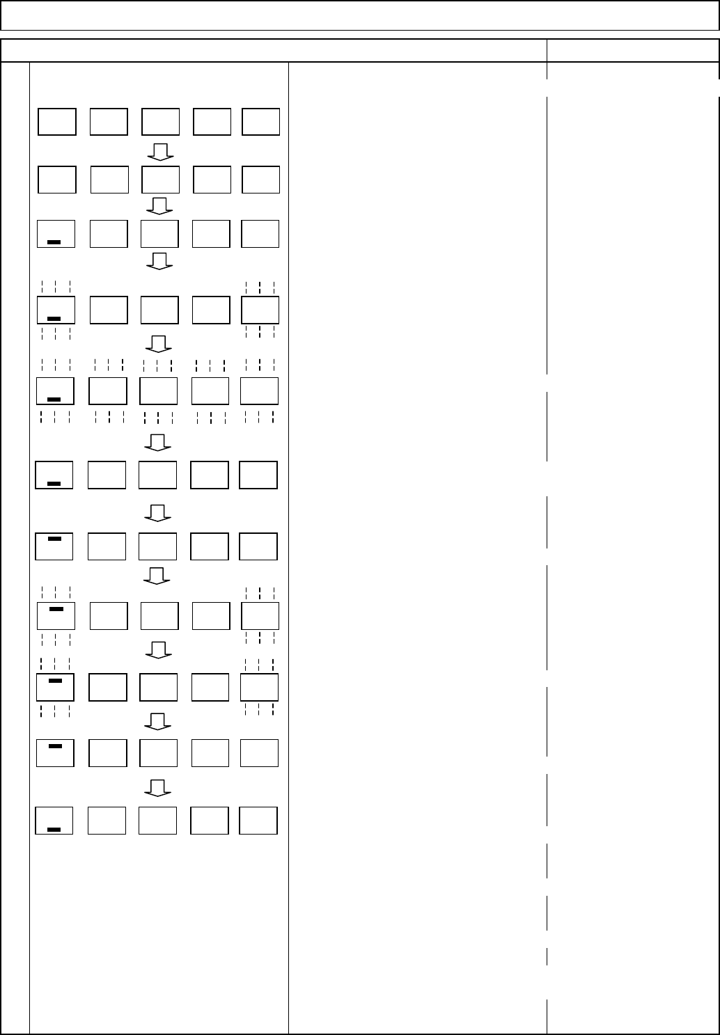
(Ex.) How to change "P A06," a 6-digit or more parameter, to "26214
4
Display "P A01" with the "MODE" switch.
Display "P A06" with the "UP" switch.
Press the "SET" switch once.
"_ 1" is displayed.
Press the "SET" switch once.
"_ 1" is blinked.
Change the value to "_2144" with the "UP" or the "DOWN" switch.
After changing the value, press the "SET" switch once.
Blinking stops and the set value is determined.
Press the "MODE" switch once.
The setting mode for the first digit from the top, "- 0" is displayed.
Press the "SET" switch once.
"- 0" is blinked.
Change the value to "- 26" with the "UP" or the "DOWN" switch.
Press the "SET" switch once.
Blinking stops and the set value is determined.
The lowest 4-digit setting mode is returned.
To move on to the next parameter,
press the "UP" and the "DOWN" switches.
Caution
To make the changed value effective, turn off and turn on the power.
Taking the same procedures, set and check the gain and filter
parameters, the expansion parameter, and input/output setting
parameters.
Press the "SET" switch once.
Tray Direct Tray
Item Remark
Driver LED indicator
P A 0 1
P A 0 6
1
1
1 4 42
1 4 42
0
0
2 6
2 6
1 4 42
EJM8A-E-SMA070205-A01-00
Page 7-2-5-6

Basic
p
arameters
Name
PA01 Control mode 0 0
PA02 Regenerative brake option 0 0
PA03 Absolute position detection system 0 0
PA04 Function selection A-1 1 0
PA05 No. of command input pulses per rotation 0 0
PA06 Electronic gear numerator
PA07 Electronic gear denominator
PA08 Auto tuning mode 1 1
PA09 Auto tuning response 23 23
PA10 In-position range 4 7
PA11 Forward rotation torque limit 100 100
PA12 Reverse rotation torque limit 100 100
PA13 Command pulse input form 10 0
PA14 Rotation direction selection 1 1
PA15 Encoder output pulse
PA16 For manufacturer setting 0 0
PA17 For manufacturer setting 0 0
PA18 For manufacturer setting 0 0
PA19 Parameter block 00AB 00AB
Gain and filter parameters
Name
PB01 Adaptive tuning mode (Adaptive filter II) 2 2
PB02
Vibration suppression control tuning mode (Advanced vibration suppression control) 00
PB03
Position command acceleration/deceleration time constant (Smoothing) 33
PB04 Feed forward gain 0 0
PB05 For manufacturer setting 500 500
PB06 Ratio of load inertial to servo motor inertia 7 8.9
PB07 Model control gain 92 62
PB08 Position control gain 139 93
PB09 Speed control gain
PB10 Speed integral compensation 8.9 13
PB11 Speed differential compensation 980 980
PB12 For manufacturer setting 0 0
PB13 Machine resonance suppression filter 1 540
PB14 Notch shape selection 1 0 210
PB15 Machine resonance suppression filter 2
PB16 Notch shape selection 2 0 0
PB17 For manufacturer setting 101 101
PB18 Low-pass filter setting
PB19 Vibration suppression control Vibration frequency setting 100 100
PB20 Vibration suppression control Resonance frequency setting 100 100
PB21 For manufacturer setting 0 0
PB22 For manufacturer setting 0 0
PB23 Low-pass filter selection 0 0
PB24 Fine vibration suppression control selection 0 0
PB25 Function selection B-1 0 0
PB26 Gain change selection 0 0
PB27 Gain change conditions 10 10
PB28 Gain change Time constant 1 1
PB29 Gain change Ratio of load inertial to servo motor inertia 7 7
PB30 Gain change Position control gain 37 37
PB31 Gain change Speed control gain 823 823
PB32 Gain change Speed integral compensation 34 34
45004500
3690 3141
Lift-axis (TL) and Extension-axis (TP) Parameter List
No.
Tray Direct Tray
TL-axis TP-axis
TL-axisNo.
2956 2484
1500
TP-axis
262144
3200
262144
3682
4000 4000
EJM8A-E-SMA070205-A01-00
Page 7-2-5-7

Gain and filter parameters
Name
PB33
Gain change Vibration suppression control Vibration frequency setting 100 100
PB34
Gain change Vibration suppression control Resonance frequency setting 100 100
PB35 For manufacturer setting 0 0
PB36 For manufacturer setting 0 0
PB37 For manufacturer setting 100 100
PB38 For manufacturer setting 0 0
PB39 For manufacturer setting 0 0
PB40 For manufacturer setting 0 0
PB41 For manufacturer setting
PB42 For manufacturer setting
PB43 For manufacturer setting 4 4
PB44 For manufacturer setting 0 0
PB45 For manufacturer setting 0 0
Expansion parameters
Name
PC01 Acceleration time constant 0 0
PC02 Deceleration time constant 0 0
PC03 S-pattern acceleration/deceleration time constant 0 0
PC04 Torque command time constant 0 0
PC05 Internal speed command 1 100 100
PC06 Internal speed command 2 500 500
PC07 Internal speed command 3
PC08 Internal speed command 4 200 200
PC09 Internal speed command 5 300 300
PC10 Internal speed command 6 500 500
PC11 Internal speed command 7 800 800
PC12 Analog speed command maximum speed 0 0
PC13 Analog torque command maximum output 100 100
PC14 Analog monitor 1 output 6 0
PC15 Analog monitor 2 output 0 1
PC16 Electromagnetic brake sequence output 100 100
PC17 Zero speed 50 50
PC18 Alarm history clear 0 0
PC19 Encoder output pulses 21 20
PC20 Station number setting 1 2
PC21 Communication function selection 100 100
PC22 Function selection C-1 0 0
PC23 Function selection C-2 0 0
PC24 Function selection C-3 0 0
PC25 For manufacturer setting 0 0
PC26 Function selection C-5 0 0
PC27 For manufacturer setting 0 0
PC28 For manufacturer setting 0 0
PC29 For manufacturer setting 0 0
PC30 Acceleration time constant 2 0 0
PC31 Deceleration time constant 2 0 0
PC32 Command input pulse multiplying factor numerator 2 1 1
PC33 Command input pulse multiplying factor numerator 3 1 1
PC34 Command input pulse multiplying factor numerator 4 1 1
PC35 Internal torque limit 2 100 100
PC36 Status display selection 0 0
PC37 Analog speed command offset 0 0
PC38 Analog torque command offset 0 0
1000 1000
1125
TL-axis TP-axis
1125
No.
No.
Tray Direct Tray
Lift-axis (TL) and Extension-axis (TP) Parameter List
1125 1125
TL-axis TP-axis
EJM8A-E-SMA070205-A01-00
Page 7-2-5-8