CM602all_EJM8AESM_Service Manual.pdf - 第1029页
Jig: FM-1934 Lift-axis height check jig Item Remark 13 Raise the lift axis 422 mm. Check the height of the lift table (extension section) and supply-section table. Put a magnetic stand and a dial gauge on the lift-table …
Remark
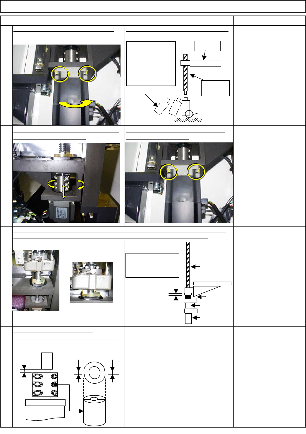
Remove the motor-holding screws. Turn the
motor so that the connector side faces forward.
Remove the motor, following the point below.
Install a new motor in the same way.
Put the coupling jig on. Position the motor
until the jig moves smoothly.
After positioning, fully tighten the motor
bolts and remove the jig.
Allen key 5 mm
M5 4 pcs.
Direct Tray
Tightening torque: 8.0N•m A=2 mm +/- 1 mm
Return the lift axis to the origin. (See Step 1.) Raise the lift with one hand, put the block gauge
(10 mm) on the stopper with the other. Lower the lift manually to sandwich the gauge.
Block gauge 10 mm
FM-0544: Centering jig
Allen key 5 mm
M5 4 pcs.
Torque wrench
Allen key 5 mm
Ruler 150 mm
M6 6 pcs.
12
Loosen the lift-axis motor coupling.
9
Item
10
11
Tray
10-mm block
gauge
Coupling
Motor
Ball screw
Origin: 10-mm
higher than the
mechanical stopper
Mechanical stopper
A
The amount of the right
and left gaps should be
the same.
Round
corner
Ball
screw
Lift
Connector
side
POINT
Using the lower
round corner of
the motor, move
the motor and pull
it out diagonally.
EJM8A-E-SMA070206-A01-00
Page 7-2-6-4
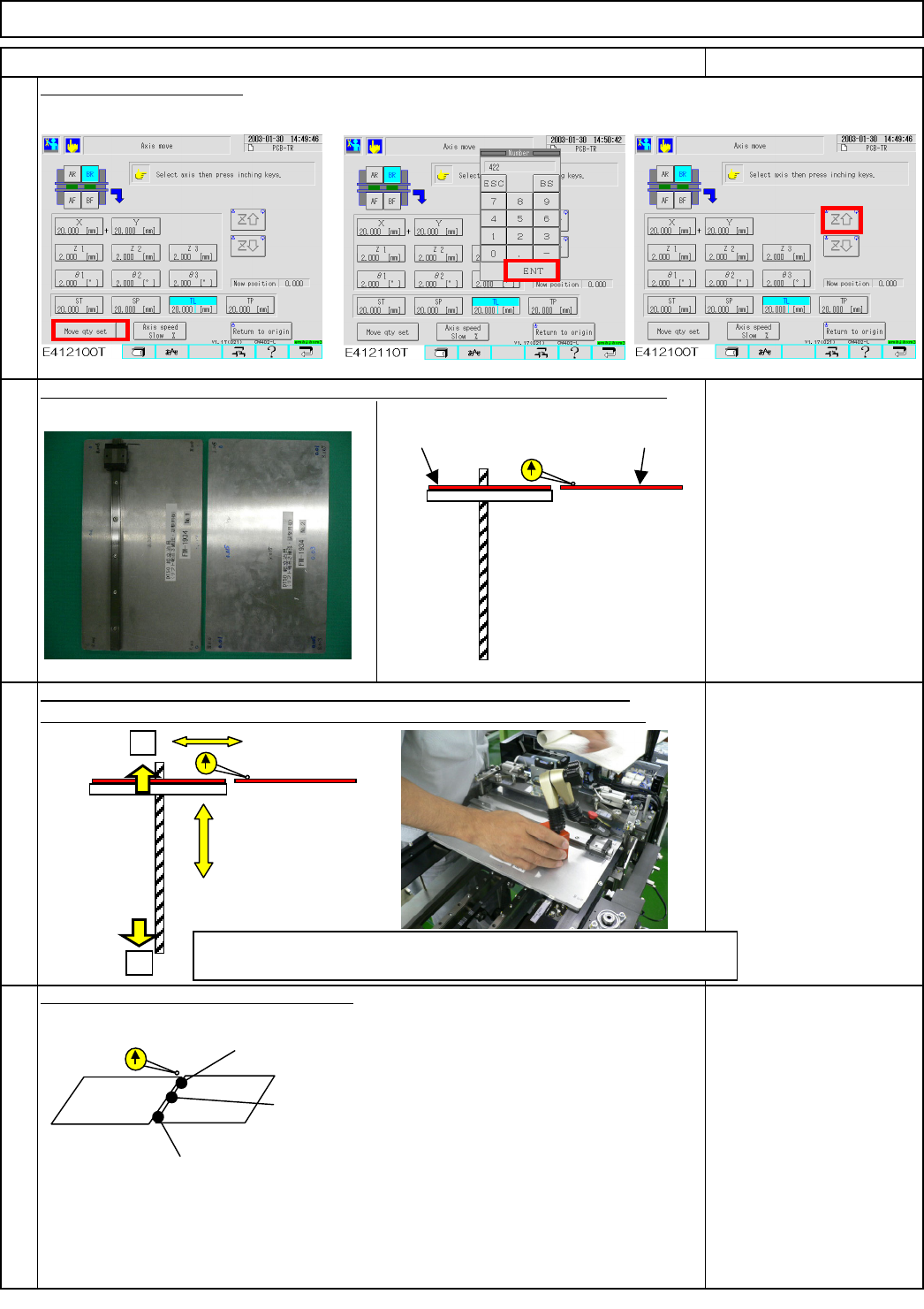
Jig: FM-1934
Lift-axis height check jig
Item Remark
13
Raise the lift axis 422 mm.
Check the height of the lift table (extension section) and supply-section table.
Put a magnetic stand and a dial gauge on the lift-table side (extension section).
Specifications: within +/-1.0
mm
Magnetic stand
Dial gauge
16
Check the three measurement positions.
14
Direct Tray
Put the palette jig on the lift table (extension section) and the supply-section table.
Tray
15
422
Inside the range: Input an offset and move on to fine-tuning. (Step 16)
Outside the range: Return to Step 11(return-to-origin process)
+
-
Specifications:
within+/-1.0
Lift table
Supply-section table
A1 (right and left): within +/- 0.2 mm
A0 (center): within +/- 0.2 mm
A1 (right and left): within +/- 0.2 mm
Lift-axis ball screw
FM-1934
FM-1934
EJM8A-E-SMA070206-A01-00
Page 7-2-6-5
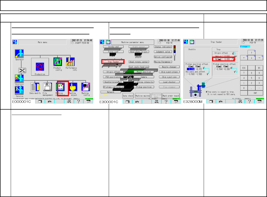
Remark
Direct Tray
Put the cover back on.
18
17
Item
Input the measurement value into TL
manually. Offset range: within +/- 1
This offset is stored in the tray, not in the
machine.
Tray
EJM8A-E-SMA070206-A01-00
Page 7-2-6-6