CM602all_EJM8AESM_Service Manual.pdf - 第1034页
the bolt shown with the arrow below. Left. Stay at the front side when tightening Right Direct Tray Item Tray Close the cover. Remark Phillips screwdriver #2 M4 screw 11 pcs. 9 EJM8A-E-SMA070207-A01-00 Page 7-2-7-4
Tray
Tighten the motor power locks with a torque
wrench. Tightening torque: 9.8N•m
After tightening, the bearing should be
turned manually. Remove the jig.
Position the dog slit at the extension position.
Position the bearing with the jig.
How to set the jig (right picture)
The dowel pin of the jig should be inside of the LM.
The hollow on the rear side of the jig should be on the
LM.
Torque wrench 9.8 N•m
Allen key 4 mm
M5 screw 4 pcs.
Jig: FM-1924
Item
5
Remark
Inch the jig gradually with a 0.05-mm pitch.
Allen key 2.5 mm
M3 screw 2 pcs.
See the followings.
Section 7-2-2 Direct Tray
Pickup Position Teaching
Section 7-2-3 Magazine
Shutter Stopper Position
8
Carry out pickup position teaching.
Position the magazine stopper.
6
7
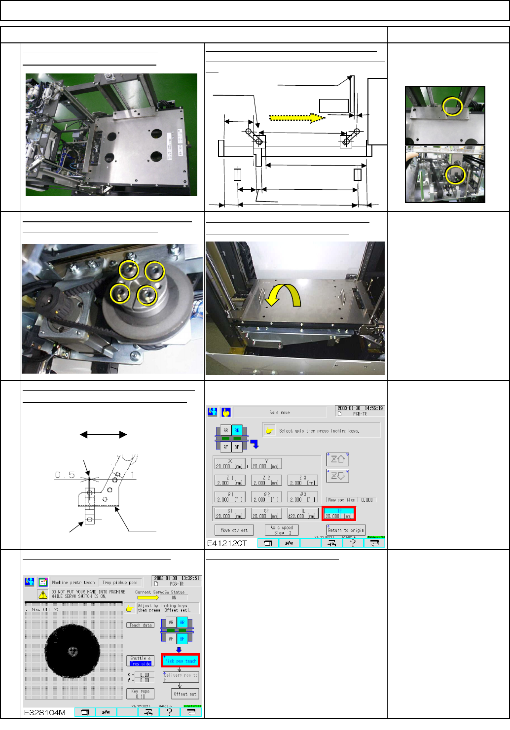
Direct Tray
A=382.5mm
Origin point
E
C
D
(392.5)
6
F
Magazine
(2)
(51)
Su
pp
l
y
section
B=9
(Magazine side)
Optical-axis
(Pickup side)
Dog
Extension-position sensor PH732
EJM8A-E-SMA070207-A01-00
Page 7-2-7-3
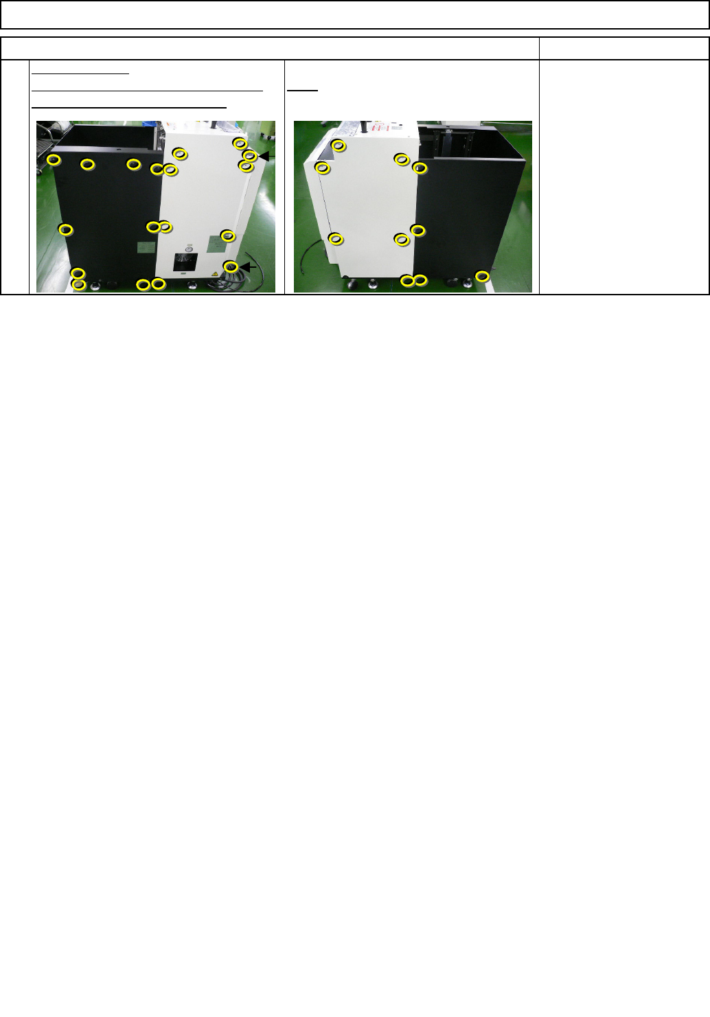
the bolt shown with the arrow below.
Left. Stay at the front side when tightening
Right
Direct Tray
Item
Tray
Close the cover.
Remark
Phillips screwdriver #2
M4 screw 11 pcs.
9
EJM8A-E-SMA070207-A01-00
Page 7-2-7-4
kgs.
80
Tray
Min.
30
Part Weight
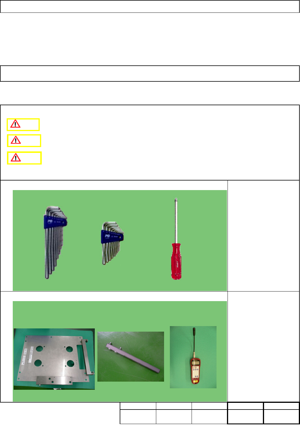
Tool
7-2-8
Torque wrench
Tension gauge
Teaching
Assembly/AdjustmentRemoval/Disassembly
10
Min. Min.
40
• This section describes the procedures for replacing the extension-axis timing belt.
Total
Extension-axis Timing Belt Replacement
Direct Tray
Jig
Jig: FM-1924
Pulley holding jig
Tension gauge
Min.
Caution
Danger
Warning
EJM8A-E-SMA070208-A01-00
Page 7-2-8-1