CM602all_EJM8AESM_Service Manual.pdf - 第1037页
Put the belt in place. Tension the belt at the motor section. Loosen B. Tension it in the order of A and B. Check Tensions F1 and F2 with a tension gauge. Tray After replacing the belt, tighten the belt- clamp section. s…
the bolt shown with the arrow below.
Tray
Rear
Remark
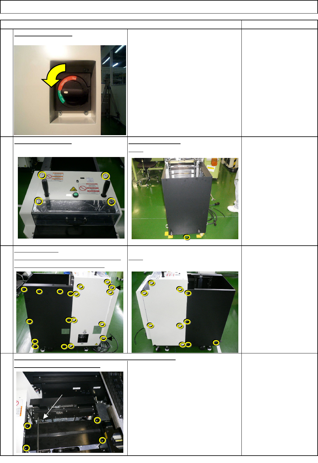
Turn off the power.
Phillips screwdriver #2
Screw M4 4 to 6 pcs.
Phillips screwdriver #2
Screw M4 14 pcs.
Remove the bolt.
Allen key 2 mm
Phillips screwdriver #1
M3 6 pcs.
Truss 6 pcs.
Open the cover.
Left. Stay at the front side when removing Right
Be careful not to drop the bolts.
3
2
1
Item
Direct Tray
Remove the cover.
4
Remove the four hexagon bolts, and then the palette table.
TP-axis
EJM8A-E-SMA070208-A01-00
Page 7-2-8-2
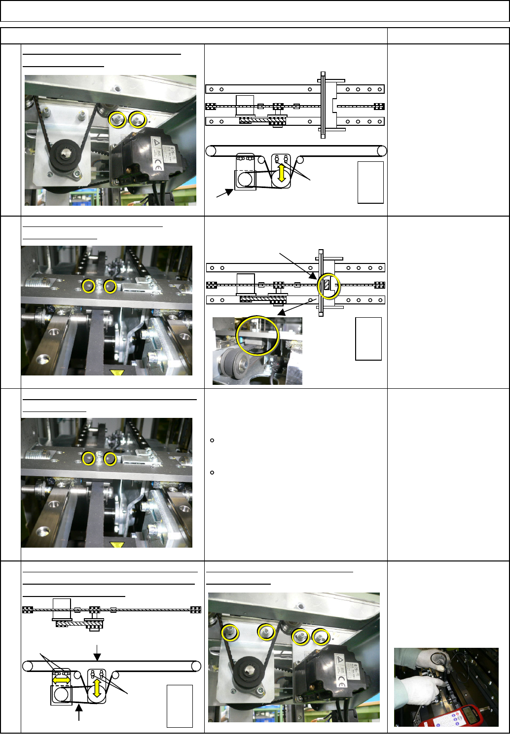
Put the belt in place. Tension the belt at
the motor section. Loosen B. Tension it
in the order of A and B.
Check Tensions F1 and F2 with a
tension gauge.
Tray
After replacing the belt, tighten the belt-
clamp section.
section. Loosen A.
Allen key 4 mm
Screw M5 2 pcs.
Remark
Tension gauge
F1 48.5+/-3Hz
F2 231 +/- 17Hz
Loosen the belt tension at the motor
Replace the belt.
Allen key 2.5 mm
Screw M3 2 pcs.
Remove the belt-clamp section.
6
7
8
Item
Direct Tray
Allen key 2.5 mm
Screw M3 2 pcs.
5
Belt clamp
Extension-axis motor
Supply
section
A
F1=48.5Hz
A
B
F2=231Hz
Supply
section
Supply
section
EJM8A-E-SMA070208-A01-00
Page 7-2-8-3
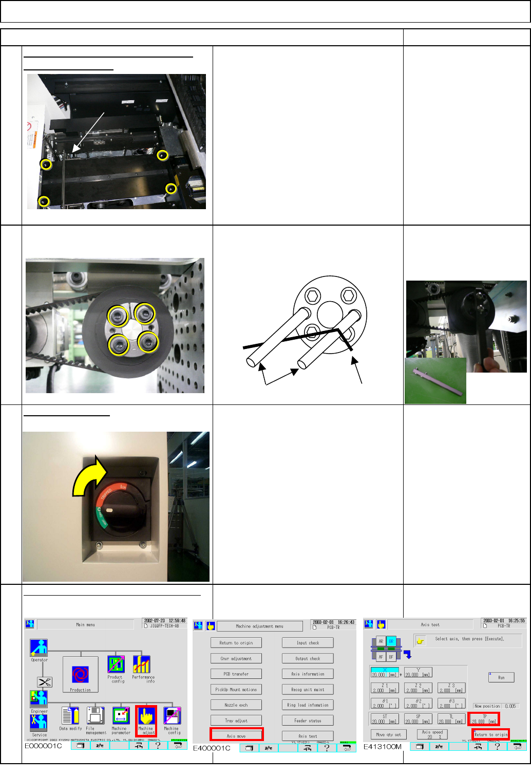
Put the palette table back on with the
four Hexagon bolts.
Return the extension-axis to the origin.
Allen key 2 mm
Phillips screwdriver #1
M3 6 pcs.
Truss 6 pcs.
Direct Tray
Item Remark
Tray
9
Allen key 4 mm
Screw M5 4 pcs.
Turn on the power.
10
11
12
TP-axis
Screw M5×40
Allen key
EJM8A-E-SMA070208-A01-00
Page 7-2-8-4