CM602all_EJM8AESM_Service Manual.pdf - 第1042页
3 4 Remove the control-box front cover. Remark Turn off the power. Remove the control-box front cover. Item Direct Tray Tray Remove the lift-axis driver. • Remove all the connectors from the front of the control box and …
Tray
Min.
kgs.
30
Direct Tray
• This section describes the procedures for replacing the extension-axis driver.
Total Part Weight
280
7-2-9 Extension-axis Driver Replacement
None
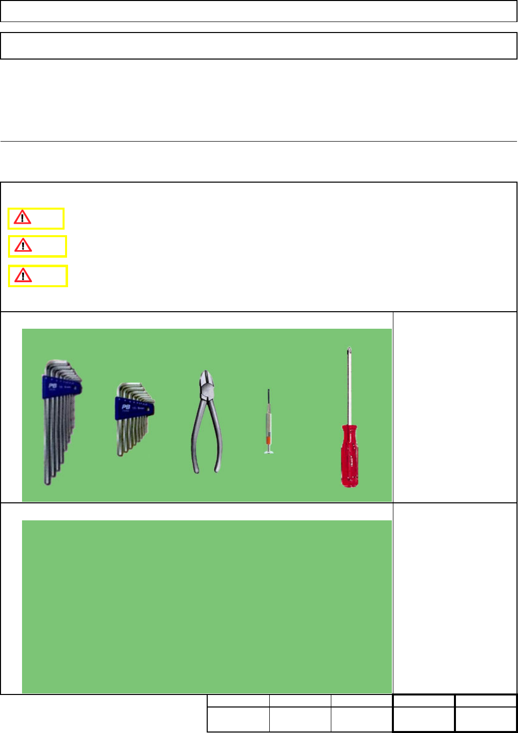
Phillips screwdriver #2
Precision screwdriver
Nippers
Allen key M4
Teaching
Assembly/AdjustmentRemoval/Disassembly
30
Min. Min. Min.
20
Tool
Jig
Caution
Danger
Warning
EJM8A-E-SMA070209-A01-00
Page 7-2-9-1
3
4
Remove the control-box front cover.
Remark
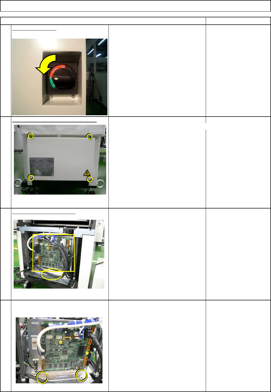
Turn off the power.
Remove the control-box front cover.
Item
Direct TrayTray
Remove the lift-axis driver.
• Remove all the connectors from the
front of the control box and from the
board.
• Remove the cable tie from the front of
the control box.
• Remove the box-holding screws.
2
1
EJM8A-E-SMA070209-A01-00
Page 7-2-9-2
8
6
7
5
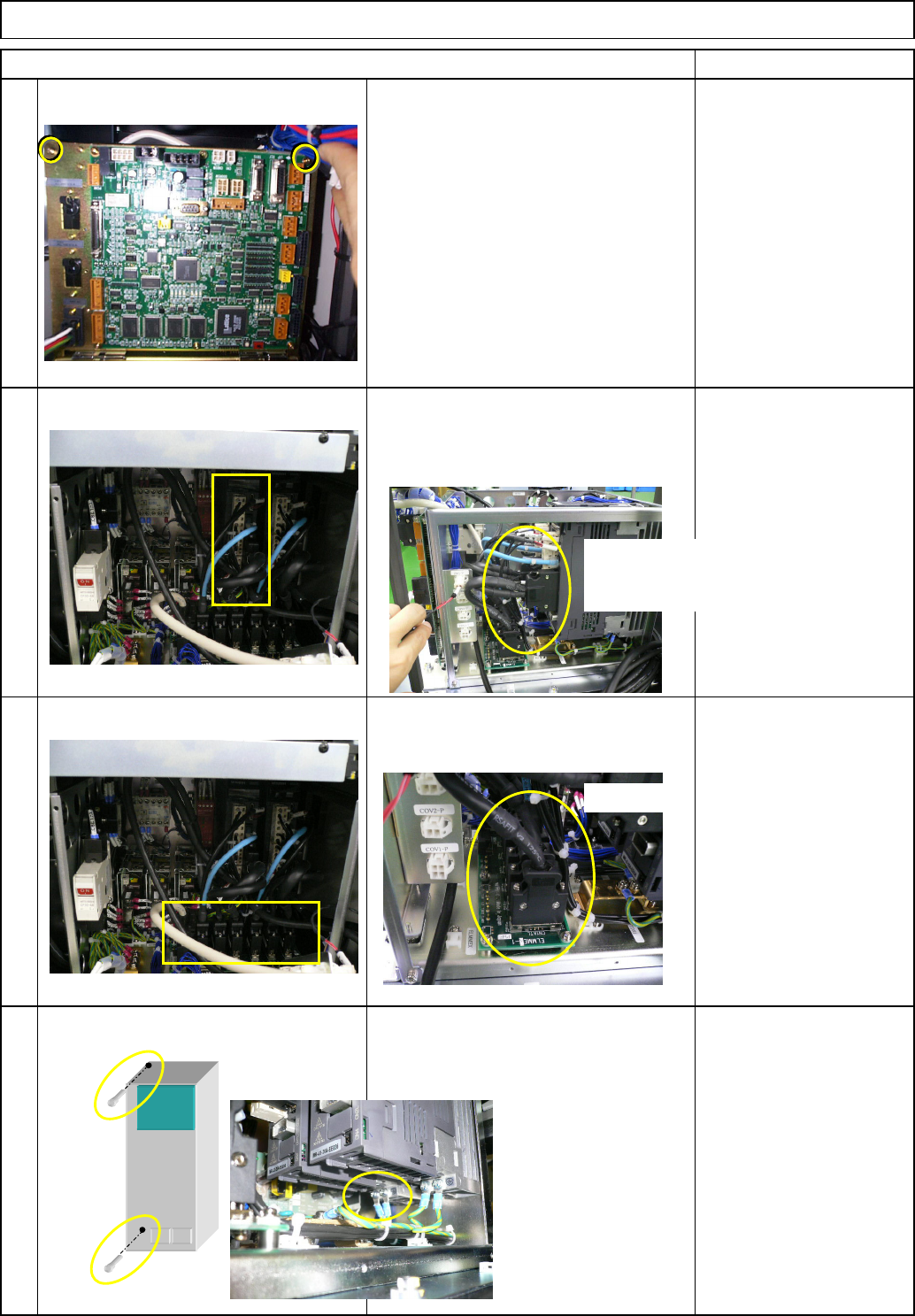
• Pull the box towards you so that the driver
can be removed easily. Remove the driver
connectors.
• Remove the earth cable and the driver-
holding scrwes, and then the driver.
• Remove the relay connector.
Direct Tray
Remark
Tray
• Remove the two screws from the upper
front side of the box.
Item
Ref. side
Front: Lift-axis
Rear: Extension-axis
Ref. side
EJM8A-E-SMA070209-A01-00
Page 7-2-9-3