CM602all_EJM8AESM_Service Manual.pdf - 第1044页
Check the driver parameters. 10 11 9 Item Remark Direct Tray • Replace the driver. Install the driver and connect the connectors in reverse order to Steps 3 to 8. * Connect the correct connectors, checking the connector …
8
6
7
5
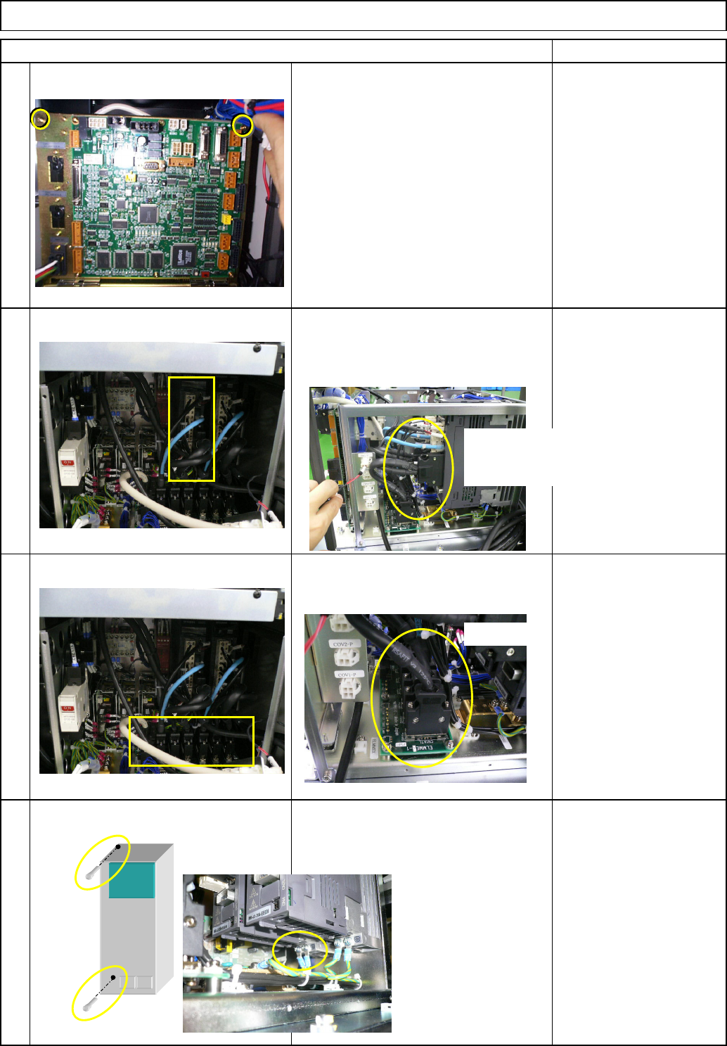
• Pull the box towards you so that the driver
can be removed easily. Remove the driver
connectors.
• Remove the earth cable and the driver-
holding scrwes, and then the driver.
• Remove the relay connector.
Direct Tray
Remark
Tray
• Remove the two screws from the upper
front side of the box.
Item
Ref. side
Front: Lift-axis
Rear: Extension-axis
Ref. side
EJM8A-E-SMA070209-A01-00
Page 7-2-9-3
Check the driver parameters.
10
11
9
Item Remark
Direct Tray
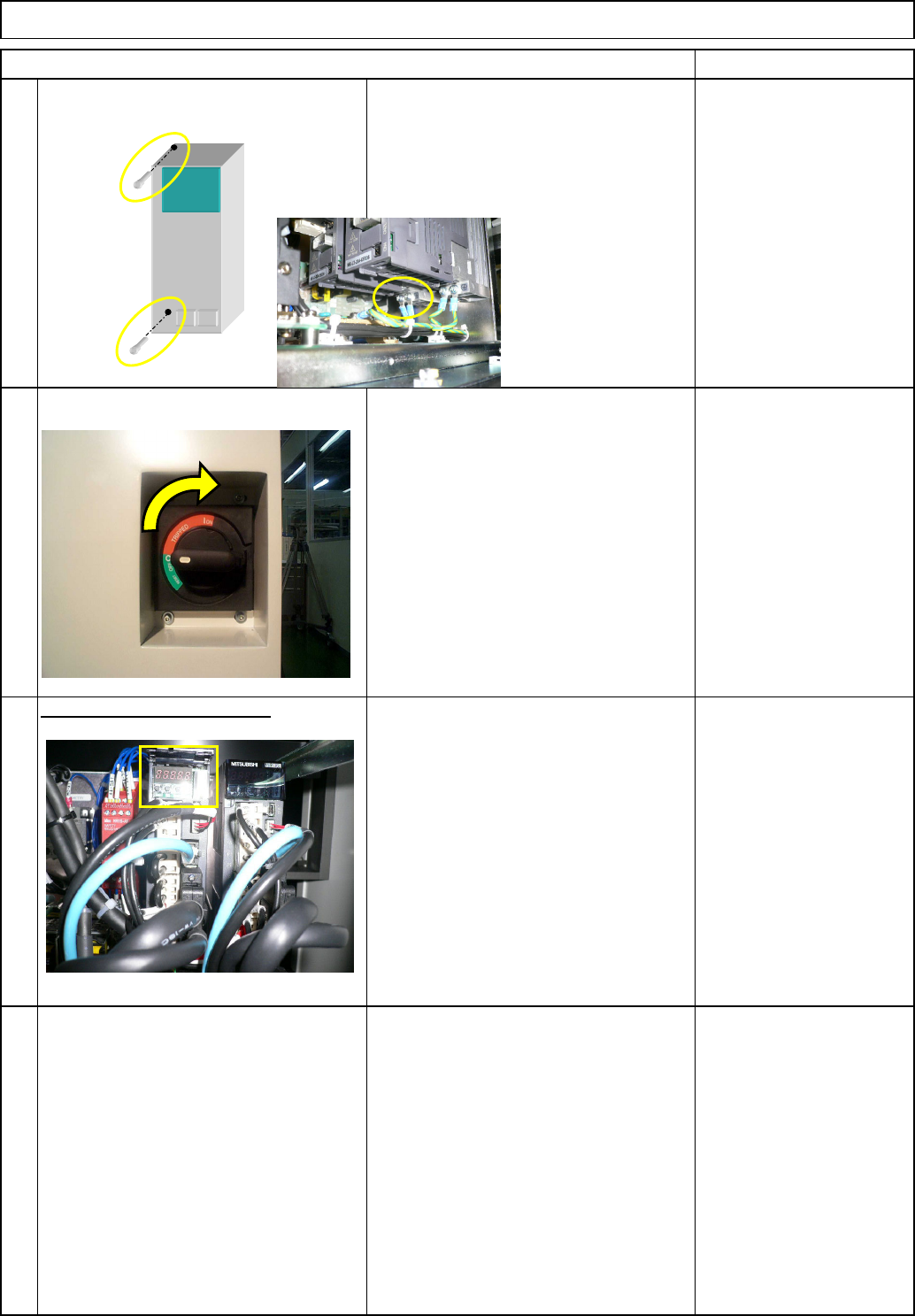
• Replace the driver. Install the driver
and connect the connectors in reverse
order to Steps 3 to 8.
* Connect the correct connectors,
checking the connector labels when
connecting them.
Tray
• After connecting the connectors, turn
on the power.
• Check the driver parameters.
• Open the driver-operation-panel cover.
Refering to the operation method and
the parameter list from the next page
onward, check and set the driver
parameters.
EJM8A-E-SMA070209-A01-00
Page 7-2-9-4
MODE switch
changes display mode, and "Low" from/to "High."
UP switch
chan
g
es dis
p
la
y
and data.
DOWN switc
h
chan
g
es dis
p
la
y
and data.
SET switch
Determines dis
p
la
y
and data.
(1) Status indicator "C"
(2) Diagnosis "rd-oF"
(3) Alarm "AL --"
(4) Basic parameter "P A01"
(5) Gain and filter parameter "P b01"
(6) Expansion setting parameter "P C01"
(7) Input/output setting parameter "P d01"
(8) Another parameter 1 "P E01"
(9) Another parameter 2 "P F01"
(10) Another parameter 3 "P o01"
Caution
To check or change a parameter, display (4) to (7).
Before changing the parameter after driver replacement,
set PA19 first.
For parameter values to be set, see the parameter list in following
pages. (8) to (10) are reserved for setting by the manufacturer.
How to check or change the parameters.
• Basic parameter: "P A01" to "P A19"
• Gain and filter parameter: "P b01" to "P b45"
• Expansion setting parameter: "P C01" to "P C50"
• Input/output setting parameter: "P d01" to "P d30"
• Another parameter 1: "P E01" to "P E40"
• Another parameter 2: "P F01" to "P F20"
• Another parameter 3: "P o01" to "P o08"
• The left shows the indication with
power ON
Pressing the "MODE" switch changes
mode as shown in (1) to (7) below.
(Ex.) How to check or change the basic parameters.
Display "P A01" with the mode switch.
Pressing the "UP" switch changes from "P A01," "P A02" to "P A03."
Pressing the "DOWN" switch changes the reading in reverse order.
Change "P A01." With "P A01" displayed, press the "SET" switch twice.
The preset parameter value blinks. The value should be 0. If not, change
that value to 0, pressing the "UP" and "DOWN" buttons as necessary.
When the value is blinking, it can be changed. After changing the set value,
pressing the "SET" switch determines the new setting. To move on to the
next parameter, press the "UP" or "DOWN" switch.
Item Remark
12
• Driver operation panel
Tray Direct Tray
Driver LED indicator
ドライバ操作部
MITSUBISHI
MR-J3
MODE UP DOWN SET
LED表示部
C
r - o Fd
A - -L
P A 0 1
P b 0 1
P C 0 1
P d 0
1
P A 0 1
0 0 00
P A 0 1
P E 0 1
P F 0 1
P o 0
1
Driver operation panel
MITSUBISHI
MR-J3
MODE UP DOWN SET
LED indicators
C
r - o Fd
A - -L
P A 0 1
P b 0 1
P C 0 1
P d 0 1
P A 0 1
0 0 00
P A 0 1
P E 0 1
P F 0 1
P o 0 1
EJM8A-E-SMA070209-A01-00
Page 7-2-9-5