CM602all_EJM8AESM_Service Manual.pdf - 第1058页
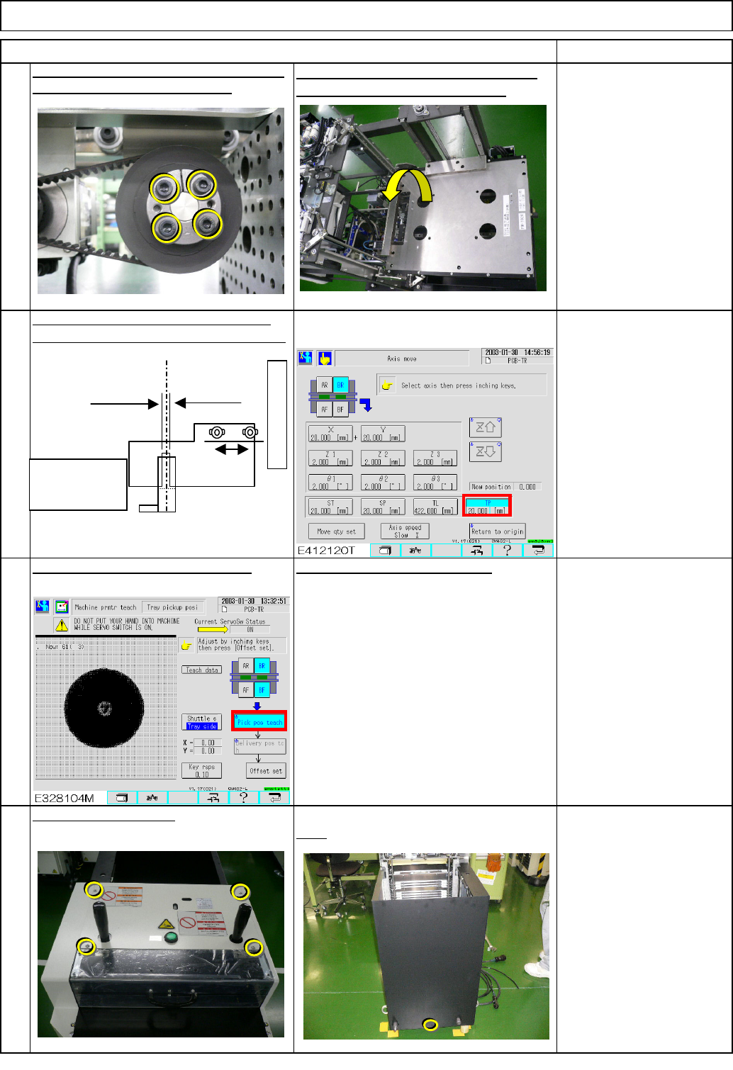
the bolt shown with the arrow below. 22 Remove the cover. Tray 23 Close the cover. Left. Stay at the front side when tightening Right Phillips screwdriver #2 Screw M4 11 pcs. Remove the bolt. Rear Phillips screwdriver #2…
19
Carry out pickup position teaching.
Rear
Phillips screwdriver #2
Screw M4 4 to 6 pcs.
20
Put the cover back on.
See the followings:
Section 7-2-2 Direct Tray
Pickup Position Teaching
Section 7-2-3 Magazine
Shutter Stopper Position
Adjustment
18
Position the dog slit at the extension-axis
position. Move the axis with a 0.1-mm pitch.
Allen key 2.5 mm
M3 screw 2 pcs.
Position the magazine stopper.
17
Torque wrench 9.8 N•m
Allen key 4 mm
M5 screw 4 pcs.
Tighten the motor power locks with a torque
wrench. Tightening torque: 9.8N•m
After tightening, the bearing should be
turned manually. Remove the jig.
Tray Direct Tray
Item Remark
Magazine side
(0.5 mm)
Lift side
(1.0 mm)
Optical-axis sensor
Extension position PH sensor PH732
Dog
Supply section
Light through: ON
Light blocked: OFF
Light blocked at the mechanical stopper
in the - (supply) direction
EJM8A-E-SMA070210-A01-00
Page 7-2-10-6
the bolt shown with the arrow below.
22
Remove the cover.
Tray
23
Close the cover.
Left. Stay at the front side when tightening Right
Phillips screwdriver #2
Screw M4 11 pcs.
Remove the bolt.
Rear
Phillips screwdriver #2
Screw M4 4 to 6 pcs.
21
Put the cover back on.
Left Right
Phillips screwdriver #2
Screw M4 14 pcs.
Direct Tray
Item Remark
EJM8A-E-SMA070210-A01-00
Page 7-2-10-7
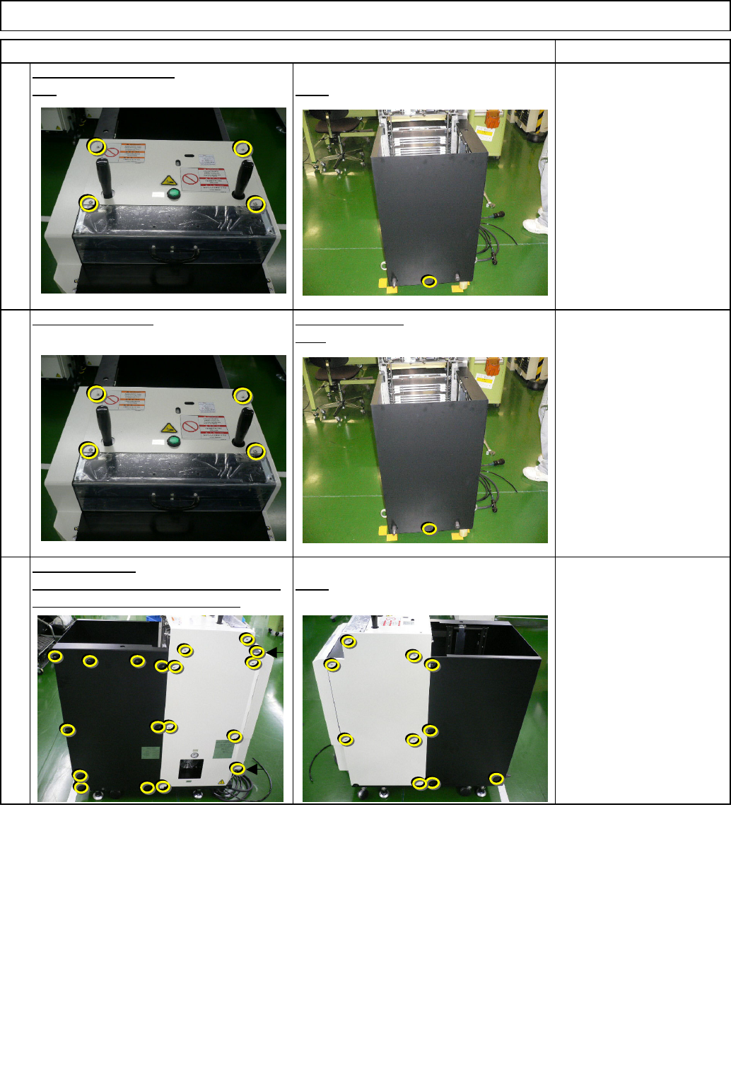
Assembly/Adjustment
Min.
kgs.
Direct TrayTray
Teaching
Jig: FM-1924
Jig: FM-1931
Jig: FM-1932
7-2-11 Adjusting the Palette Shift Detection Sensor
• This section describes the procedures for adjusting the palette shift detection sensor.
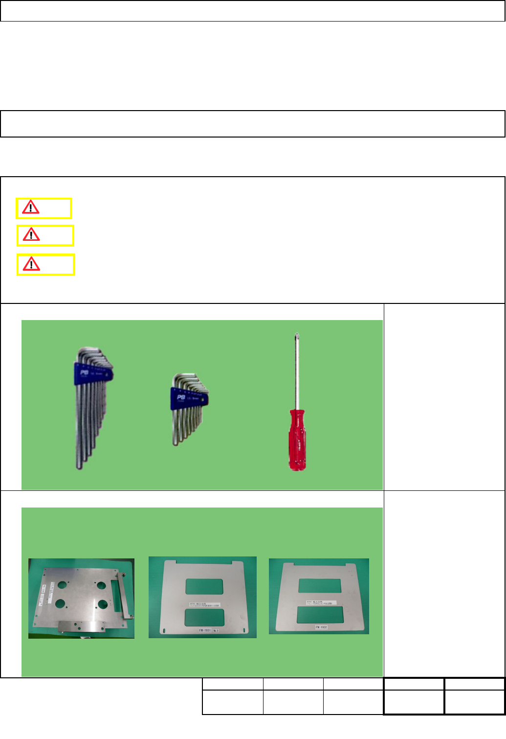
Tool
Phillips screwdriver #2
Allen key
Level
Removal/Disassembly
Jig
Total Part Weight
40
Min. Min.
40
Min.
FM-1931
FM-1932
FM-1924
Caution
Danger
Warning
EJM8A-E-SMA070211-A01-00
Page 7-2-11-1