CM602all_EJM8AESM_Service Manual.pdf - 第1061页
Palette j i g FM-1931 Palette j i g FM-1931 Palette j i g FM-1932 5 6 Item Direct Tray Remove the palette jig from the lowest level of the lower magazine. Put it on the supply section again. Check the light is emitted. I…
Jig: FM-1924
Level: (0.02 mm/division)
shift detection PH.
Palette
j
i
g
FM-1931
4
Remark
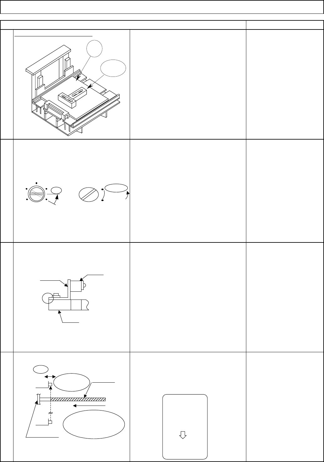
Put the palette jig on the supply section.
Slide the upper sensor (light-sensing device)
and fix the sensor in place immediately
before the sensor is turned off.
Aligning the end of the metal plate with
that of the FB, fix the sensor in place
provisionally.
* The light-sensing device: upper
position,
the light-emitting device: lower
position.
2
Using the palette jig, adjust the palette
X and Y directions: within 0.1 mm/m
Using the jig and levels, level the
extension section.
1
Item
Level the extension section.
Tray
Set the sensor volume to 88%
(horizontal)
Set the switch to L.ON.
Direct Tray
3
Jig
Level
Adjust the
volume to
88% (horizontal).
SENS
MAX
88%
Horizontal
Set the switch
to L.ON.
L.ON
D.ON
A
Metal plate
PH
FB
Insert until it
makes contact
with the shutter.
Shutte
r
Light-
sensin
g
Palette jig
Slide
Immediately
before the
sensor is
turned OFF
LED (red) is
ON
EJM8A-E-SMA070211-A01-00
Page 7-2-11-2
Palette
j
i
g
FM-1931
Palette
j
i
g
FM-1931
Palette
j
i
g
FM-1932
5
6
Item
Direct Tray
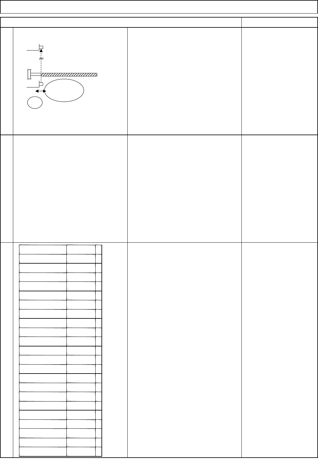
Remove the palette jig from the lowest
level of the lower magazine. Put it on the
supply section again. Check the light is
emitted. If blocked, re-adjust the upper
sensor (light-sensing device).
Put one palette jig on each following
section at the same time: supply section,
lowest level of the upper magazine and
lowest level of the lower magazine.
Check light is emitted by checking the
sensor LED (when three jigs are
inserted).
Remark
If light is blocked, re-adjust the lower
sensor (light-emitting).
7
Remove the palette jig from the supply
section. Put it on the lowest level of the
lower magazine. Slide the lower sensor
(light-emitting device), fix the sensor in
place immediately before the sensor is
turned off.
Remove the palette jig FM-1931. Check
light is blocked at each level separately:
from supply position to the lowest
position, using the palette jig FM-1932.
* LED red: Light off/LED green: Light ON
LED (red): Light off (blocked)
Put one palette on each level and check
the sensor emits light.
LED (red) on (light-emitting)
Tray
Light-
emitting
Slide
Slot position Conclusion
Supply OK/NG
NG palette
OK/NG
Palette OK/NG
OK/NG
3rd level OK/NG
4th level OK/NG
5th level OK/NG
6th level OK/NG
7th level OK/NG
8th level OK/NG
9the level OK/NG
10th level OK/NG
11th level OK/NG
12th level OK/NG
13th level OK/NG
14th level OK/NG
15th level OK/NG
16th level OK/NG
17th level OK/NG
18th level OK/NG
19th level OK/NG
20th level OK/NG
1st level
2nd level
EJM8A-E-SMA070211-A01-00
Page 7-2-11-3
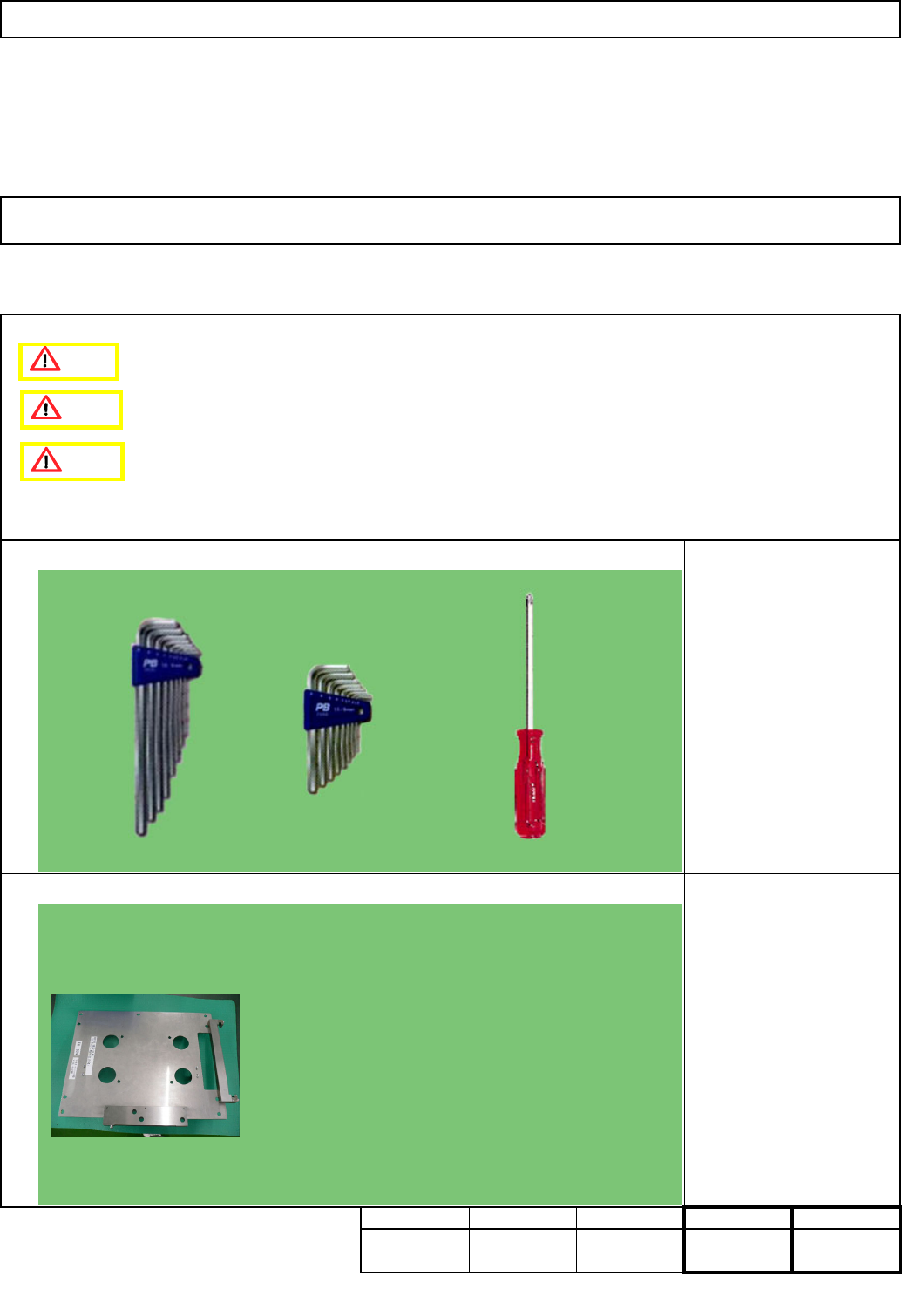
Tool
20
Jig
Jig: FM-1924
Min.
Phillips screwdriver #2
Allen key
Level
Total Part Weight
7-2-12 Palette Detection Sensor Adjustment
Min.Min. Min.
Tray
kgs.
20
Teaching
Assembly/AdjustmentRemoval/Disassembly
Direct Tray
• This section describes the procedures for adjusting the palette detection sensor.
FM-1924
Caution
Danger
Warning
EJM8A-E-SMA070212-A01-00
Page 7-2-12-1