CM602all_EJM8AESM_Service Manual.pdf - 第1071页
Control Hard Control Box Diagram 8-2-1 CPU Box Control Box Dia g ram 8-2 See the control cable layout. (Separate manual) See "2. Control Box Diagram 2-1 CPU Box." EJM8A-E-SMA080201-A01-00 Page 8-2-1-1
Control Hard
Control Hard
Contorl Unit
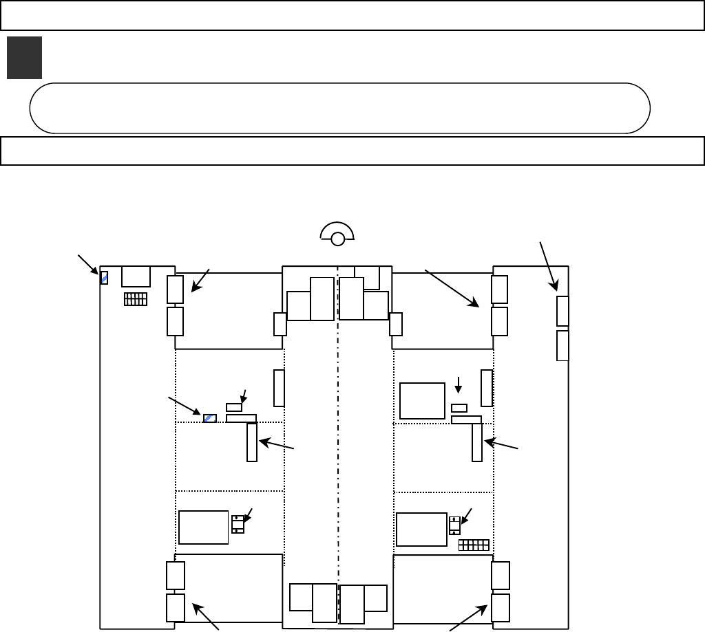
8-1-1 Layout
Control Unit
8-1
6
5
8
Vacuum
pump
DR7 DR8
DR5 DR6
Main SW
NF0ECX
Feeder control board
FDD
NF0ECX
Feeder control board
DR2 DR1
Feeder control board Feeder control board
DR4 DR3
θaxis
powe
r
CPU
BOX
Line camera change
CNT board
NF28CX
Y
axis
X
axis
Y
axis
X
axis
Y
axis
X
axis
POWER
UNIT#1
AC terminal
box
LED
light source
#2
#1
Vacuum
pump
TB5
TB4
NF0ECX NF0ECX
LED
light source
#9
θ-axis
powe
r
#5
POWER
UNIT#2
NF2ACX
NF2ACX
Earth plateEarth plate
Y
axis
X
axis
HUB board
NF8BCX
#4
#3
#C
#D
#A
#B
①⑯
D9
width
adjustment
DA
width
adjustment
Earth plate
Earth plate
EJM8A-E-SMA080101-A01-00
Page 8-1-1-1
Control Hard
Control Box Diagram
8-2-1 CPU Box
Control Box Dia
g
ram
8-2
See the control cable layout.
(Separate manual)
See "2. Control Box Diagram
2-1 CPU Box."
EJM8A-E-SMA080201-A01-00
Page 8-2-1-1
Control Hard
Contorl Box Diagram
8-2-2 Power Box
See the control cable layout.
(Separate manual)
See "2. Control Box Diagram
2-2 Power Box."
EJM8A-E-SMA080202-A01-00
Page 8-2-2-1