CM602all_EJM8AESM_Service Manual.pdf - 第135页
Maintenance Adjustment Main Body Beam Maintenance Adjustment ・ Tools Phillips screwdriver #2 Allen key 2.5 mm Allen key 3 mm Wrench 7 mm ・ Jig FM-0442 : Line Camera Teaching Jig 4-1-1 Chip Recognition Camera Theta Positi…
Maintenance Adjustment Main Body Beam
Maintenance Adjustment
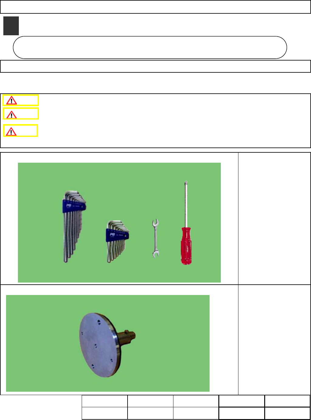
・Tools
Phillips screwdriver #2
Allen key 2.5 mm
Allen key 3 mm
Wrench 7 mm
・Jig
FM-0442:
Line Camera Teaching Jig
4-1-1 Chip Recognition Camera Theta Positioning
This section describes the procedures for positioning the chip recognition camera in the theta direction.
This positioning must be carried out when the chip recognition camera is replaced.
Be careful not to damage the glass of the chip recognition camera assembly
while working.
Caution
Dange
r
Warning
Assembly
Adjustment
10min.
Teaching
20min.
Total Time Weight of
Part
Removal
Disassembly
10min.
40min.
kgs
4
Main Bod
y
Beam
4-1
EJM8A-E-SMA040101-A01-00
Page 4-1-1-1
Maintenance Adjustment Main Body Beam
Remarks
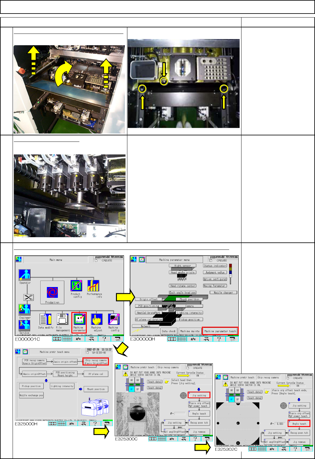
Remove the feeder cover and the chute.
Phillips screwdriver #2
Allen key 3 mm
Screw M4 2 pcs.
Screw M4-10 3 pcs.
Thick washer 3 pcs.
Fit the jig onto Nozzle 3.
Line camera teaching jig
Teach "Chip Recognition Camera" - [Theta-axis origin offset] and [Angle teach].
Section 4-2-4
3
1
Item
2
EJM8A-E-SMA040101-A01-00
Page 4-1-1-2