CM602all_EJM8AESM_Service Manual.pdf - 第158页
Maintenance Adjustment Main Body Beam Remarks Item Allen key 3 mm Iron plate Screw M4 See the sections at right. Section 4-2-5 Section 4-2-7 13 14 Remove the support pins. Carry out the following teaching. Determining th…
Maintenance Adjustment Main Body Beam
Remarks
Item
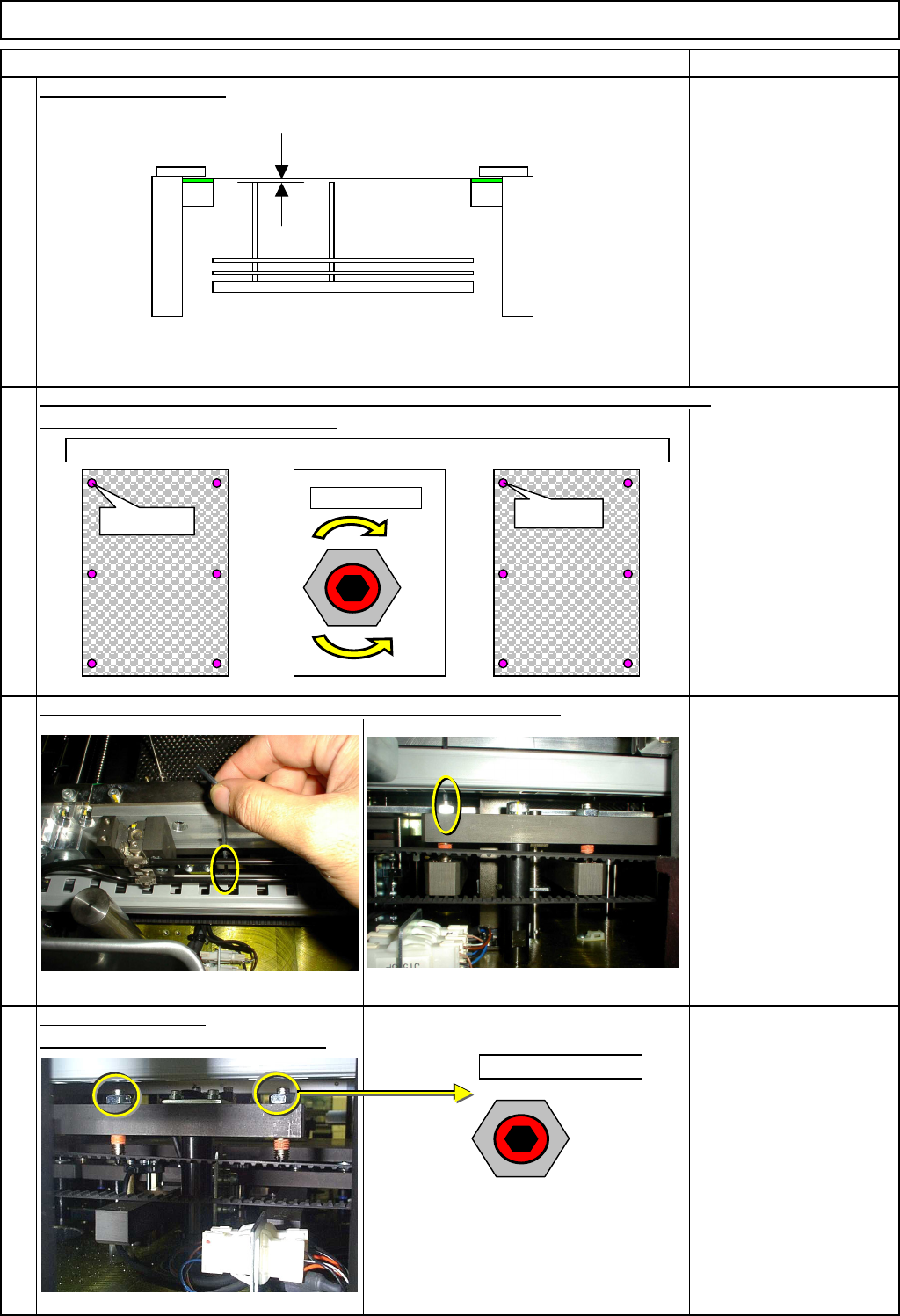
Check reference height.
H: 0.00 mm to -0.10 mm
Measure the height of the pins and record the values so that the current values can be
Using the height of the
fixed transfer rail and the
stopper, carry out the
adjustment.
Specifications:
0 +/- 0.02 mm
Allen key 2.5 mm
Tighten the four nuts.
(two nuts at the front; two at the rear)
Wrench 13 mm
compared with those after adjustment.
11
12
10
Adjust the height, turning the screws in the nuts loosened in Step 7.
9
Top of screw
Top of screw
Down
Up
-0.05
-0.1
-0.05
0.1
-0.070.0
Reference
0.0
-0.02
-0.01
0.0
-0.010.0
Reference
NG OK
Fixed side
Movable side
H
Max. height to which the support
plates are raised.
The support plates should be lower than the fixed transfer belt.
Fixed transfer rail
EJM8A-E-SMA040106-A01-00
Page 4-1-6-4
Maintenance Adjustment Main Body Beam
Remarks
Item
Allen key 3 mm
Iron plate
Screw M4
See the sections at right.
Section 4-2-5
Section 4-2-7
13
14
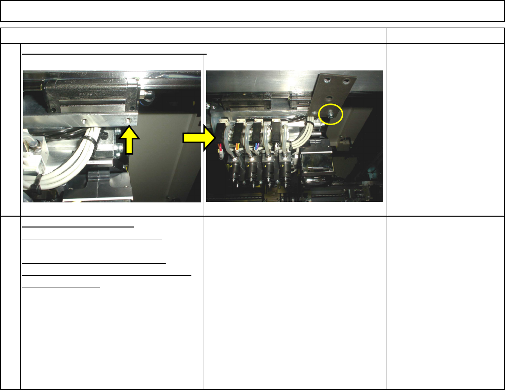
Remove the support pins.
Carry out the following teaching.
Determining the Mounting Height
and Positioning the Board
Mounting Position
Confirm the height. Remove the iron plate.
EJM8A-E-SMA040106-A01-00
Page 4-1-6-5
Maintenance Adjustment Main Body Beam
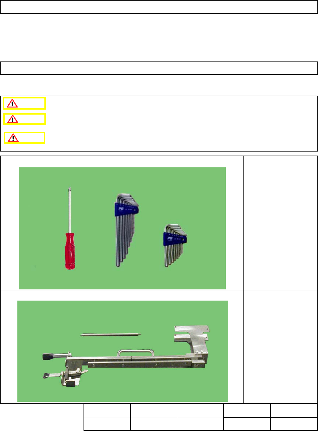
・Tools
Phillips screwdriver #2
Allen key 2.5 mm
Tape (opaque)
・Jig
FM-1055
Tape Float Sensor
Adjusting jig
4-1-7 Tape Float Sensor Adjustment
This section describes the procedures for adjusting the tape float sensor.
Caution
Dange
r
Warning
Assembly
Adjustment
10min.
Teaching
min.
Total Time Weight of
Part
Removal
Disassembly
10min.
20min.
kgs
EJM8A-E-SMA040107-A01-00
Page 4-1-7-1