CM602all_EJM8AESM_Service Manual.pdf - 第166页
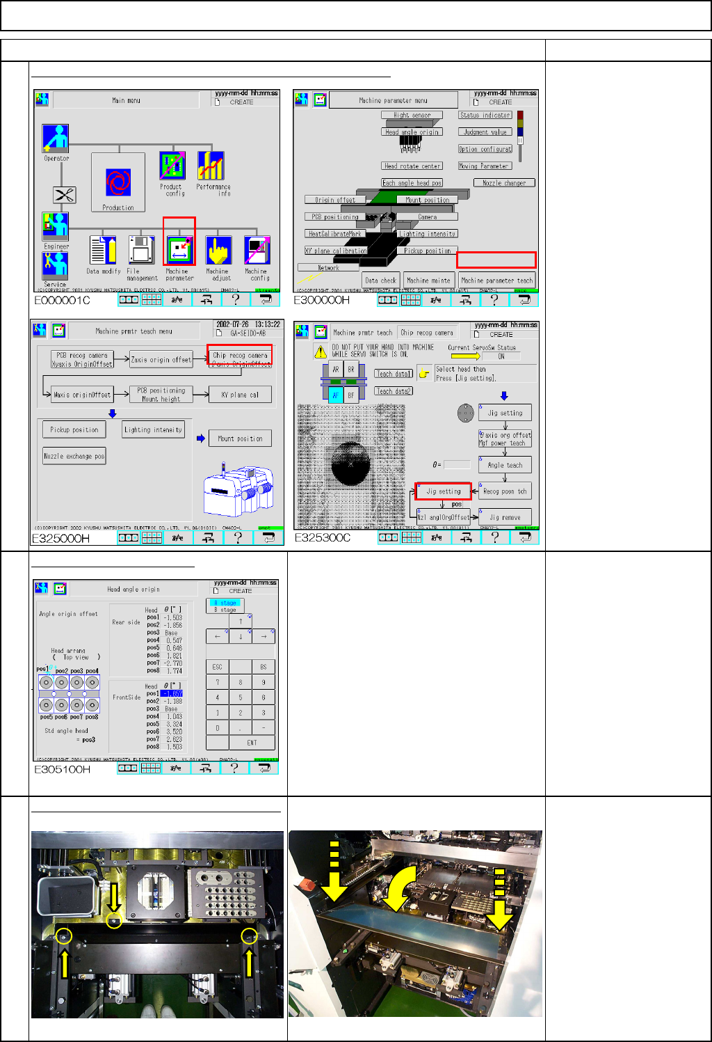
Maintenance Adjustment Main Body Beam Remarks Item Teach "Chip recognition camera - Theta-axis origin offset." Section 4-2-4 "Head angle origin" screen 画面 305000 Specifications: within +/- 5° Put back…
Maintenance Adjustment Main Body Beam
Remarks
Item
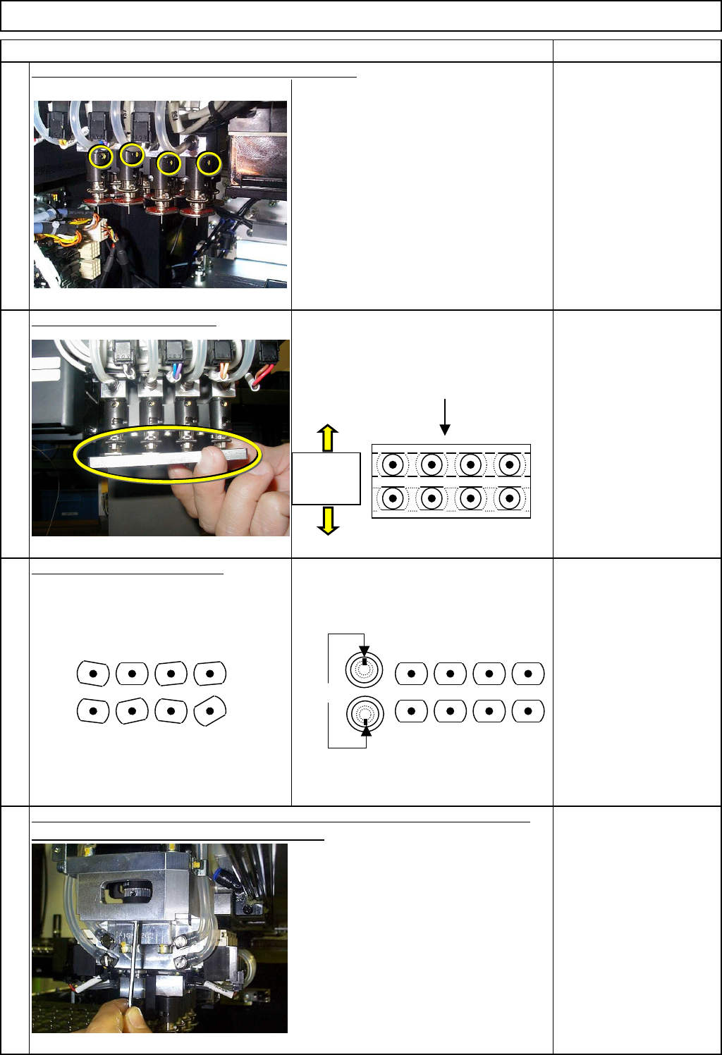
Do not loosen the set-screw of
Nozzle Holder 3. Allen key 1.5 mm
Set the jigs on Nozzles 1 to 4.
Nozzle 3: Reference
Nozzle angle adjusting jig
Adjust the theta of the nozzles.
Position the nozzle holders so that the
nozzle holder set-screws face outwards. The set-screws and the
spline of Nozzle Holders 1
to 4 should be positioned
opposite those of Nozzle
Holders 5 to 8.
Rotating the theta motor, find the point at which the jig can be inserted smoothly.
Once the point is found, tighten the set-screws.
Allen key 1.5 mm
Loosen the set-screws of Nozzle Holders 1, 2 and 4.
5
6
8
7
1
7685
4 23 1
7685
4 23
NG OK
Set-screws
Nozzle holder
set-screws
should face
outwards.
Nozzle angle
adjusting jig
1
7
685
423
EJM8A-E-SMA040108-A01-00
Page 4-1-8-3
Maintenance Adjustment Main Body Beam
Remarks
Item
Teach "Chip recognition camera - Theta-axis origin offset."
Section 4-2-4
"Head angle origin" screen
画面305000
Specifications:
within +/- 5°
Put back the feeder cover and the chute.
Close the cover.
Phillips screwdriver #2
Allen key 3 mm
Screw M4 2 pcs.
Screw M4-10 3 pcs.
Thick washer 3 pcs.
゚
11
10
9
EJM8A-E-SMA040108-A01-00
Page 4-1-8-4
Weigh
t
o
f
Part
20 min. min.
Removal
Disassembly
A
ssembl
y
Adjustment
Teaching
Total Time
20 min.20
min
.
60
Kgs
.
Main Body BeamMaintenance Adjustment
Phillips screwdriver #2
Allen key 4 mm
Wrench 7 mm
4-1-9 Lead Checker Height Adjustment
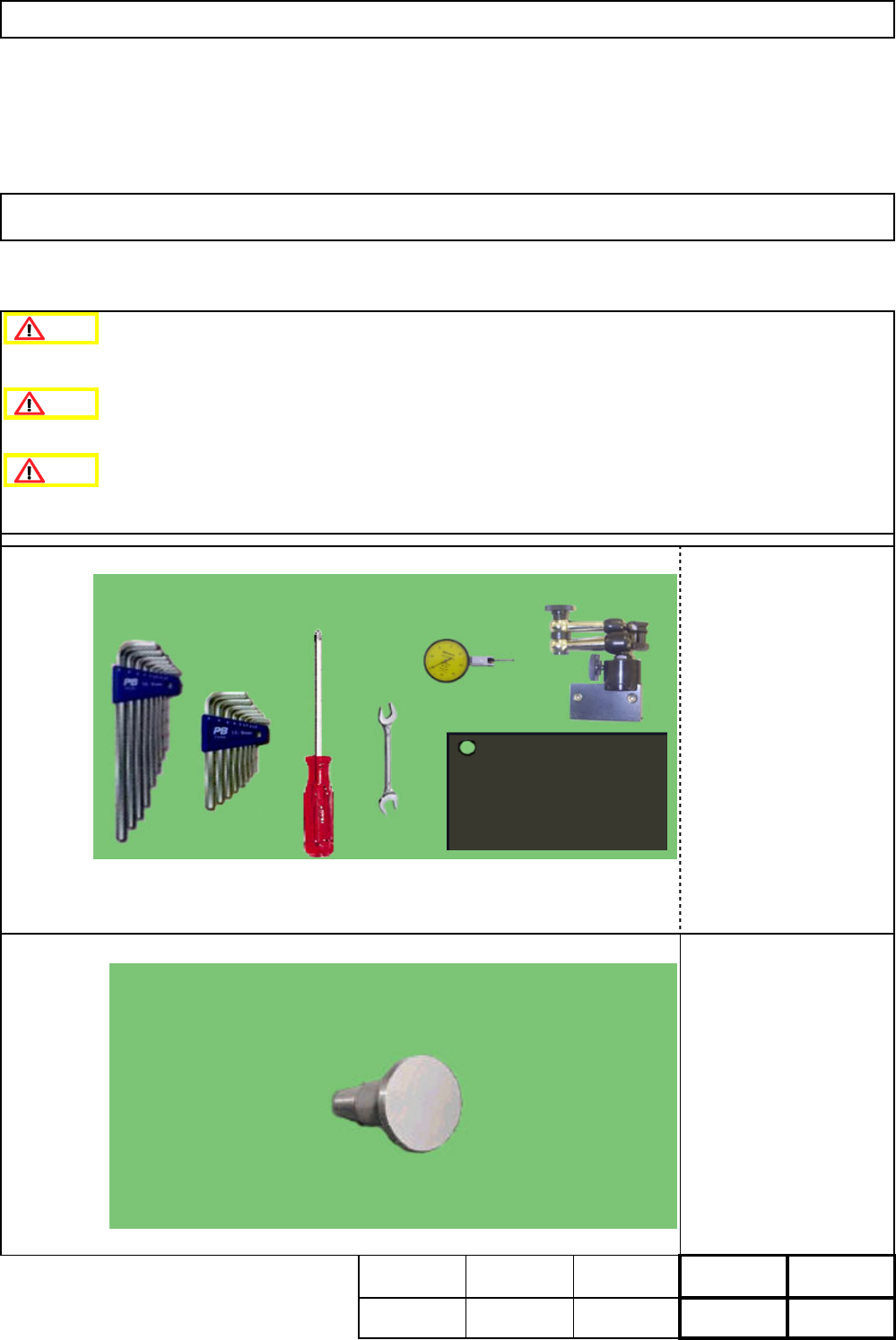
・Tools
This section describes the procedures for adjusting the height of the lead checker.
FM-1137
Laser Recognition Jig
・Jig
Caution
Danger
Warning
EJM8A-E-SMA040109-A01-00
Page 4-1-9-1