CM602all_EJM8AESM_Service Manual.pdf - 第214页
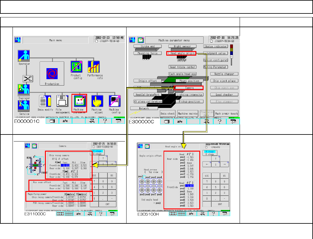
Maintenance Adjustment Light Transfer-Head Assembly (8 nozzles) Remarks Item Offsets are entered in the screens below: Offset range X, Y& θ offset (High, Middle & Low speeds) X : -5.0 to +5.0 Y : -5.0 to +5.0 θ :…
Maintenance Adjustment Light Transfer-Head Assembly (8 nozzles)
Remarks
Item
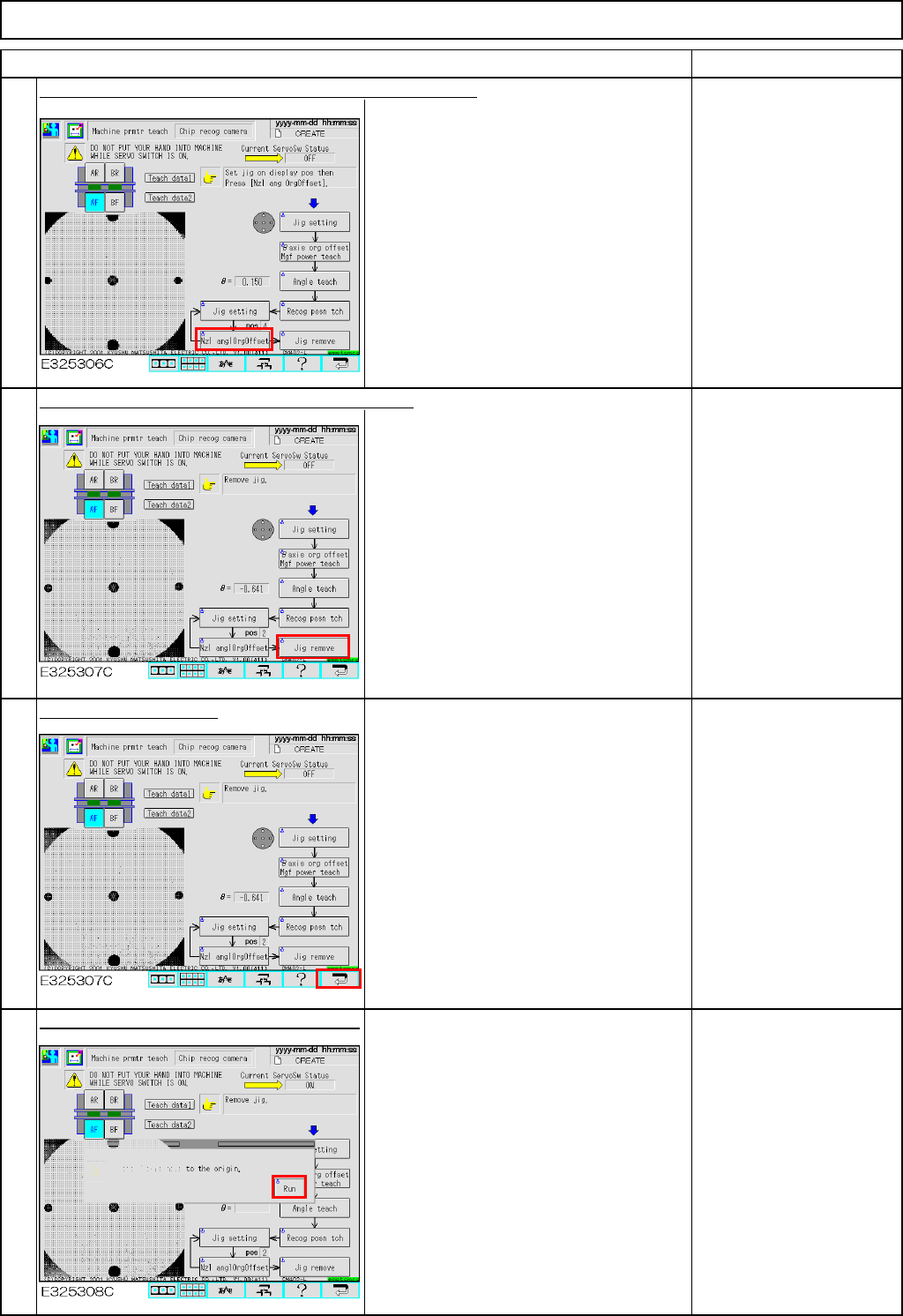
Press [Unlock] and [Nzl angleOrgOffset] simultaneously.
An offset for each θangle origin is
entered.
Teach in the following
order: Positions 4, 5, 6, 7,
8, 1 and 2, repeating
Steps 10 to 12.
Press [Unlock] and [Jig remove] simultaneously.
The head moves to the jig setting
position (over the NG box).
Remove the jig from
Position 2, which is the
last position.
Press the [Return] key.
Press [Unlock] and [Run] simultaneously.
All axes of the selected stage return to
the origin.
14
15
13
16
EJM8A-E-SMA040204-A01-00
Page 4-2-4-5
Maintenance Adjustment Light Transfer-Head Assembly (8 nozzles)
Remarks
Item
Offsets are entered in the screens below:
Offset range
X, Y&θ offset
(High, Middle & Low speeds)
X :-5.0 to +5.0
Y :-5.0 to +5.0
θ :-0.1 to +1.0
* Reverse scan offset
(High, Middle & Low speeds)
Reverse scan:0.0 to 0.75
* Magnifying power
X Mag. :0.017 to 0.018
Y Mag. :0.017 to 0.018
* Head angle origin
θ: -5.0 to +5.0
17
18
EJM8A-E-SMA040204-A01-00
Page 4-2-4-6
Maintenance Adjustment Light Transfer-Head Assembly (8 nozzles)
This section describes the procedures for determining the mounting height and for positioning the board.
・Tools
None
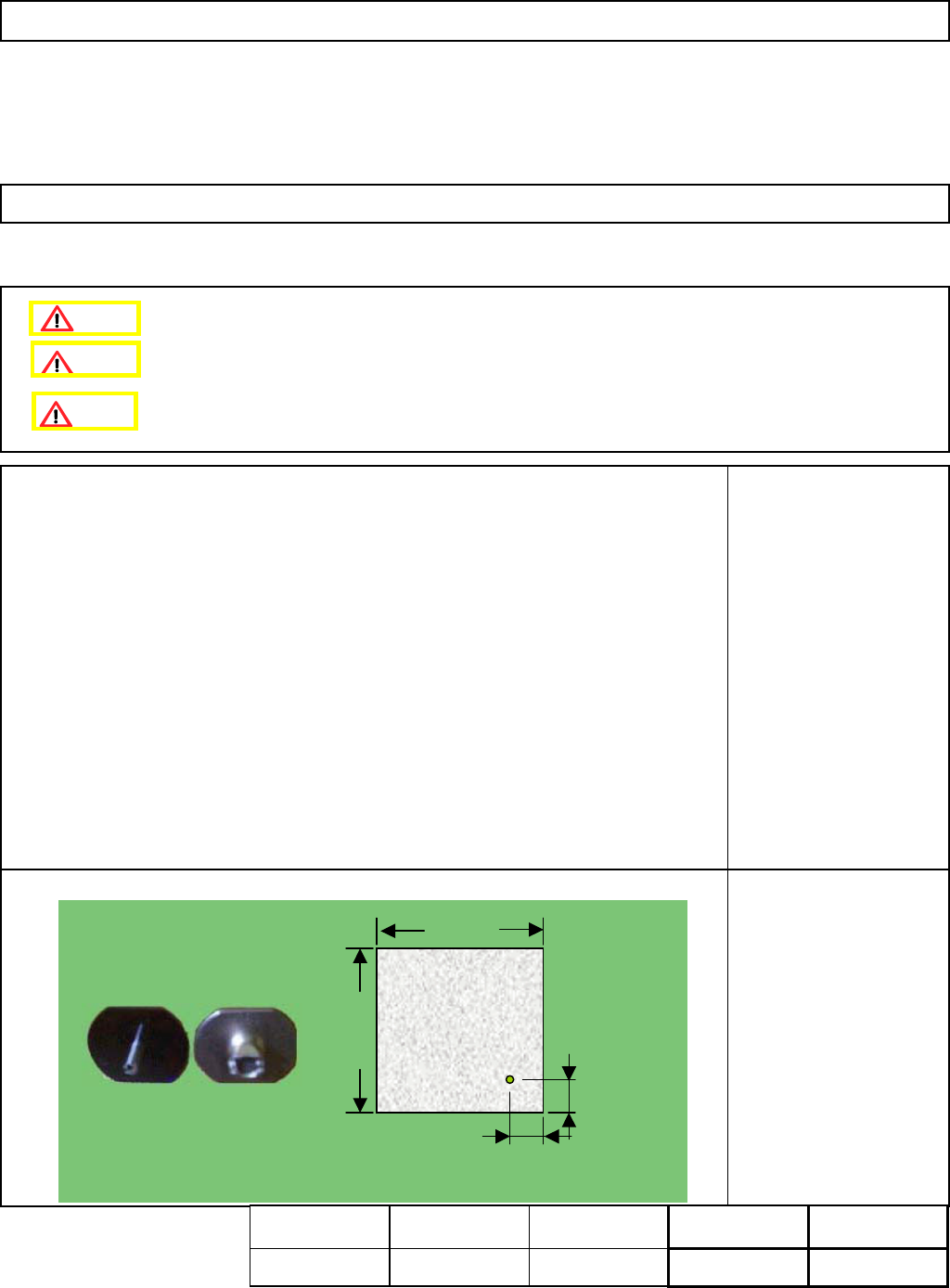
・Jig
FM-1074
Board jig 50 mm x 50 mm
(with a hole)
Nozzle 130
4-2-5 Determining the Mounting Height and Positioning the Board
Remove the support pins beforehand.
10 +/- 0.05 mm
10 +/- 0.05 mm
50 mm
50 mm
t= 3.0 mm
Assembly
Adjustment
min.
Teaching
5min.
Total Time Weight of
Part
Removal
Disassembly
min.
5min.
kgs
Caution
Dange
r
Warning
EJM8A-E-SMA040205-A01-00
Page 4-2-5-1