CM602all_EJM8AESM_Service Manual.pdf - 第219页
Maintenance Adjustment Light Transfer-Head Assembly (8 nozzles) Remarks Item Press [Unlock] and [Run] simultaneously. The X- and the Y-axes of the selected stage return to the origin. Press [PCB positioning Mount height]…
Maintenance Adjustment Light Transfer-Head Assembly (8 nozzles)
Remarks
Item
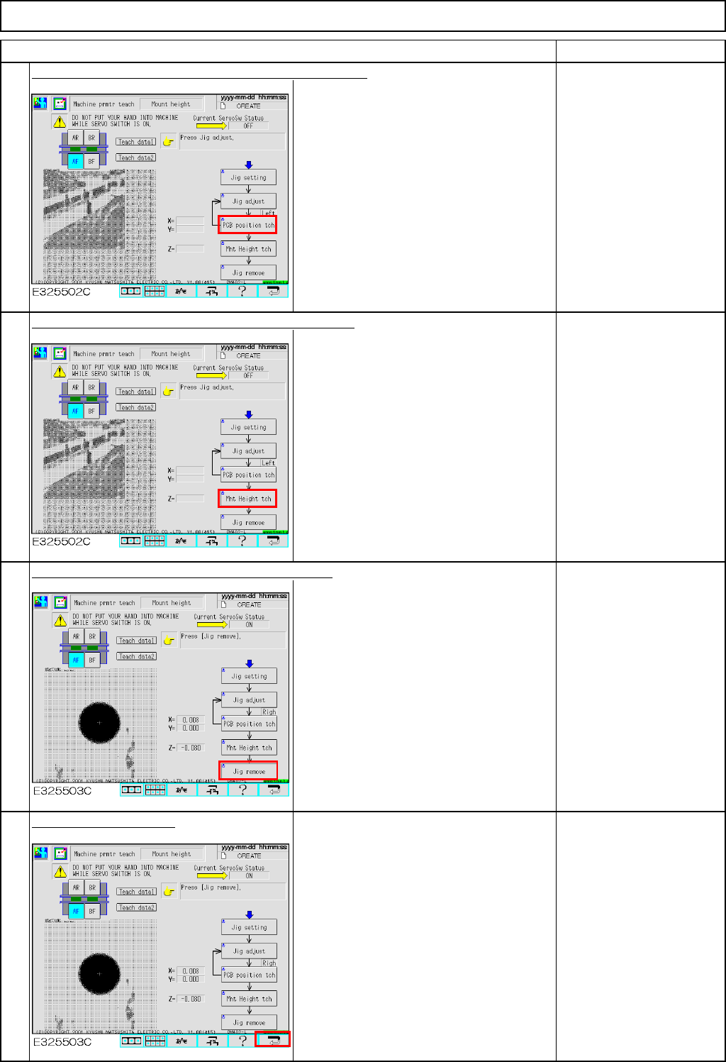
Press [Unlock] and [PCB position tch] simultaneously.
The head camera recognizes the jig hole
so that the offset for the hole position will
be entered automatically.
Press [Unlock] and [Mnt Height tch] simultaneously.
With the nozzle descending to and
ascending from the jig, the vacuum
pressure is measured and the offset is
set automatically.
Press [Unlock] and [Jig remove] simultaneously.
The head moves to the nozzle setting
position (over the NG box).
Remove the nozzle and
the jig.
Press the [Return] key.
To save the parameter,
press the [Return] key.
9
10
11
12
EJM8A-E-SMA040205-A01-00
Page 4-2-5-4
Maintenance Adjustment Light Transfer-Head Assembly (8 nozzles)
Remarks
Item
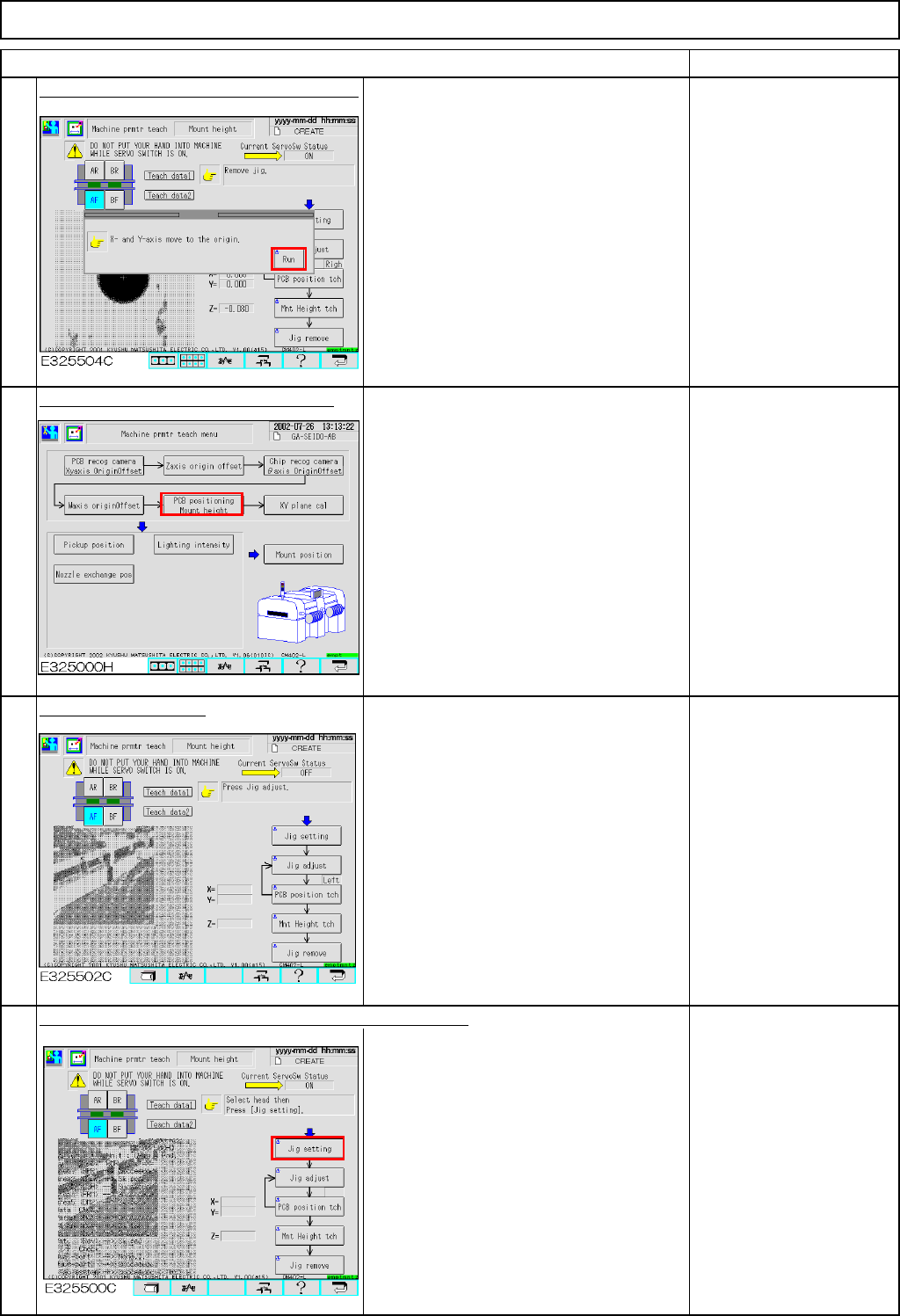
Press [Unlock] and [Run] simultaneously.
The X- and the Y-axes of the selected
stage return to the origin.
Press [PCB positioning Mount height].
Select the rear stage.
Press the "Unlock" key and [Jig setting] simultaneously.
Fit Nozzle 130 onto
Nozzle Position 3.
13
14
15
16
EJM8A-E-SMA040205-A01-00
Page 4-2-5-5
Maintenance Adjustment Light Transfer-Head Assembly (8 nozzles)
Remarks
Item
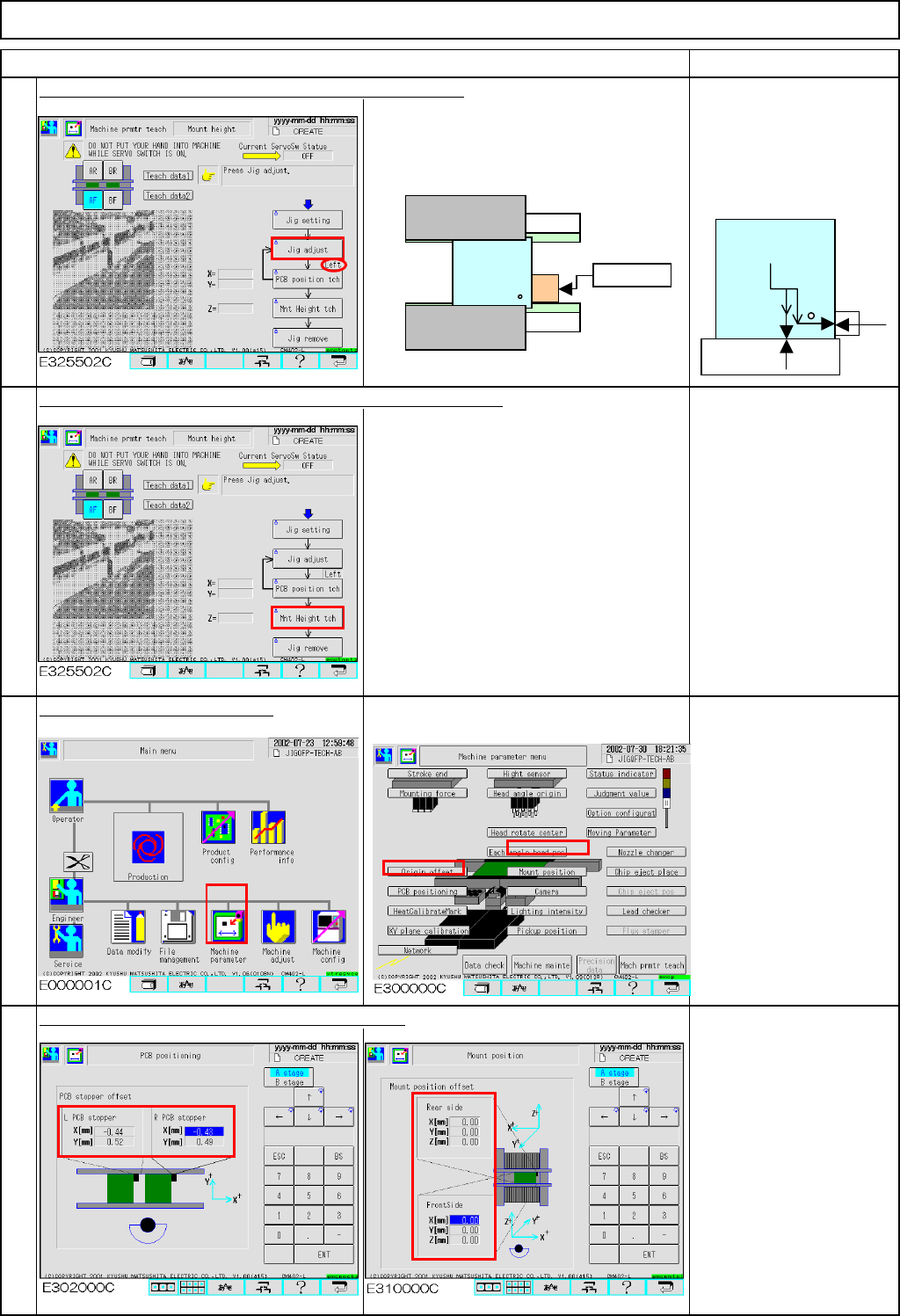
Press the "Unlock" key and [Jig adjust] simultaneously.
Check that "Left" is selected for the jig
position. Press the jig against the board
clamp holding guide and the board
stopper.
Be careful of the
orientation of the jig.
(The hole of the jig should
face the stopper and the
fixed guide.)
Press the "Unlock" key and [Mnt Height tch] simultaneously.
While the nozzle ascends and descends
above the jig, the vacuum pressure is
measured and the offset is set
automatically.
Only the mounting height is taught on the
rear side.
Check the data after teaching.
19
The offsets are entered into the screens below:
Offset range:
Board stopper offset:
X: -2.0 mm to +2.0 mm
Y: -2.0 mm to +2.0 mm
Mounting position offset:
X: -1.0 mm to +1.0 mm
Y: -1.0 mm to +1.0 mm
Z: -1.0 mm to +1.0 mm
18
20
17
Stopper
Fixed guide
There should
be no gap.
EJM8A-E-SMA040205-A01-00
Page 4-2-5-6