CM602all_EJM8AESM_Service Manual.pdf - 第253页
Maintenance Adjustment Light Transfer-Head Assembly (3 nozzles) ・ Tools None ・ Jig None 4-3-2 Board Recognition Camera --- X and Y-axis Origin Offset This section describes the procedures for entering the offset for the …
Maintenance Adjustment Light Transfer-Head Assembly (3 nozzles)
Remarks
Item
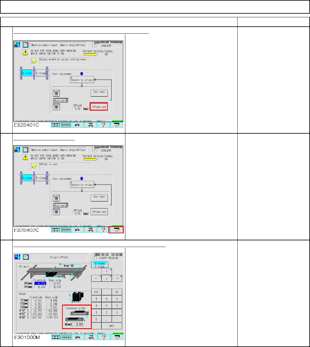
Once the adjustment is finished, press [Offset set].
The preset offset is changed to the new
one.
Press the [Return] key.
Max: 460 mm+/-0.2 mm
Min: 50 mm+/-0.2 mm
The offset is entered automatically into the screen below:
Offset range:
0.00mm to +5.00mm
5
6
7
EJM8A-E-SMA040301-A01-00
Page 4-3-1-3
Maintenance Adjustment Light Transfer-Head Assembly (3 nozzles)
・Tools
None
・Jig
None
4-3-2 Board Recognition Camera --- X and Y-axis Origin Offset
This section describes the procedures for entering the offset for the origin of the X- and the Y-axes of the board
recognition camera.
Assembly
A
d
j
ustment
min.
Teaching
2min.
Total Time Weight of
Part
Removal
Disassembl
y
min.
2min.
kgs
Caution
Dange
r
Warning
EJM8A-E-SMA040302-A01-00
Page 4-3-2-1
Maintenance Adjustment Light Transfer-Head Assembly (3 nozzles)
Remarks
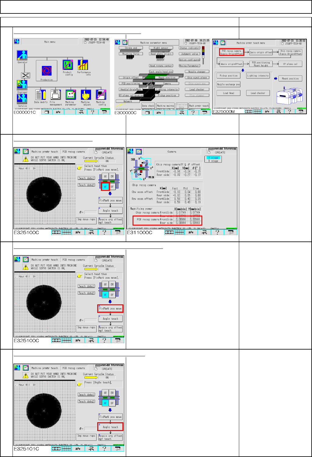
Press [PCB recog camera Xyaxis OriginOffset].
Select the stage to be taught.
If "0" is displayed in the
"Magnifying power" boxes
shown at left, enter a
tentative value of 0.01.
Press [Unlock] and [FixMark pos move] simultaneously.
The head camera for the selected stage
moves to the heat calibration mark.
The head camera recognizes the mark.
The offsets for the X- and the Y-axes are
entered.
If adjustment of the X and
Y-axis origin fails, the
mark is not displayed on
the window.
Press [Unlock] and [Angle teach] simultaneously.
The head camera recognizes the mark.
The offset for the angle of the camera is
entered.
"Angle teach" error:
If the theta is out of the
range of +/- 0.5°, this
error will occur.
See Section 4-1-2
"Head Camera
Adjustment
-Focus and Theta"
1
Item
2
3
4
EJM8A-E-SMA040302-A01-00
Page 4-3-2-2