CM602all_EJM8AESM_Service Manual.pdf - 第268页
Maintenance Adjustment Light Transfer-Head Assembly (3 nozzles) Remarks Press [PCB positioning Mount height]. Be sure to remove the support pins beforehand since the width of the conveyor is adjusted in this step. The co…
Maintenance Adjustment Light Transfer-Head Assembly (3 nozzles)
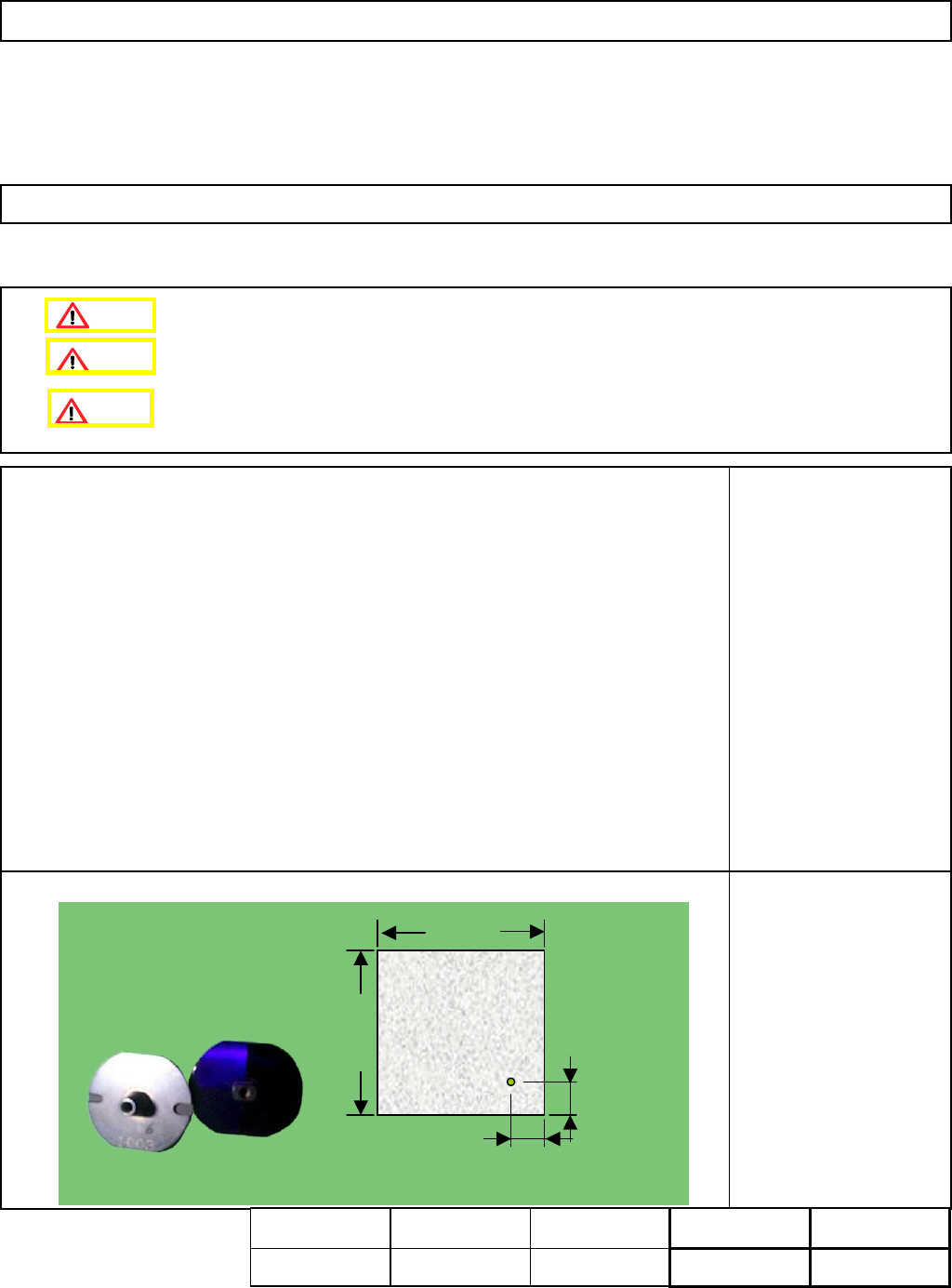
This section describes the procedures for determining the mounting height and for positioning the board.
Tools
None
Jig
FM-1074
Board jig 50 mm x 50 mm
(with a hole)
Nozzle 1003
4-3-5 Determining the Mounting Height and Positioning the Board
Remove the support pins beforehand.
10±0.05㎜
10±0.05㎜
50㎜
50㎜
t= 3.0㎜
10 +/- 0.05 mm
10 +/- 0.05 mm
50 mm
50 mm
t= 3.0 mm
Assembly
A
d
j
ustment
min.
Teaching
5 min.
Total Time Weight of
Part
Removal
Disassembl
y
min.
5 min.
kgs
Caution
Dange
r
Warning
EJM8A-E-SMA040305-A01-00
Page 4-3-5-1
Maintenance Adjustment Light Transfer-Head Assembly (3 nozzles)
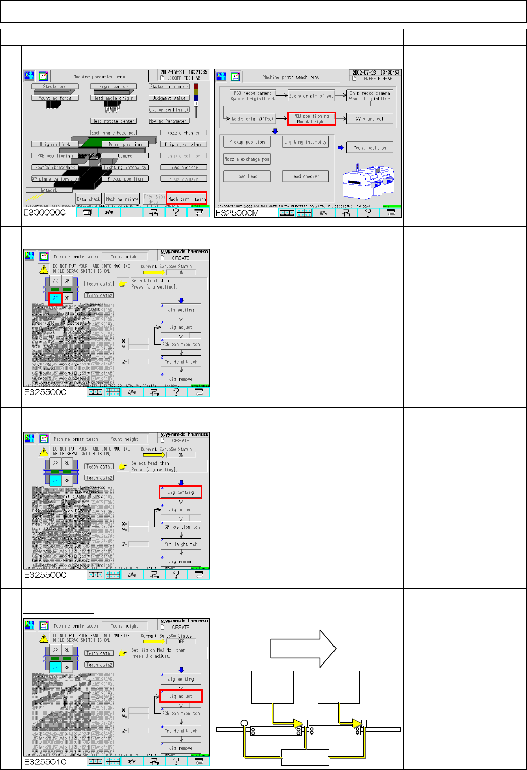
Remarks
Press [PCB positioning Mount height].
Be sure to remove the
support pins beforehand
since the width of the
conveyor is adjusted in
this step.
The conveyor will be
adjusted to a width of 50
mm.
Select the stage to be taught.
Press [Unlock] and [Jig setting] simultaneously.
Set Nozzle 1003 on
Nozzle Position 3.
Press [Unlock] and [Jig adjust]
The head moves away. The board
simultaneously.
stopper at the 2nd mounting position
moves up.
To change "Right" to
"Left," press [Jig adjust].
The 2nd mounting
position is positioned left
when you see the stage;
check that "Left" is
selected.
Item
2
3
4
1
Flow of
boards
2nd
mounting
position
1st
mounting
position
Stoppers
EJM8A-E-SMA040305-A01-00
Page 4-3-5-2
Maintenance Adjustment Light Transfer-Head Assembly (3 nozzles)
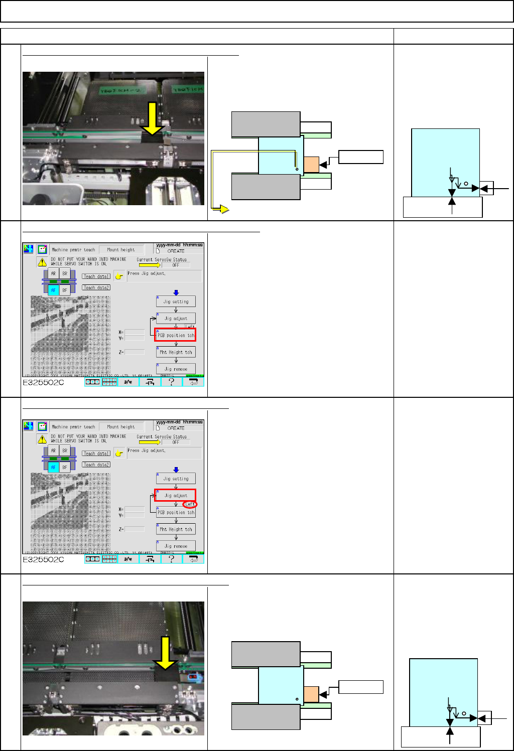
Remarks
Item
Place the board jig on the 2nd mounting position.
Firmly press the board jig against the
fixed guide and the board stopper.
Take care with the
orientation of the jig;
the hole on the jig should
face the stopper and the
fixed guide.
Press [Unlock] and [PCB position tch] simultaneously.
The head camera recognizes the jig hole
so that the offset for the hole position will
be entered automatically.
Press [Unlock] and [Jig adjust] simultaneously.
The head moves away. The board
stopper at the 1st mounting position
moves up.
Check that the jig is
positioned at right.
Set the board jig on the first mounting position.
Firmly press the board jig against the
fixed guide and the board stopper.
Take care with the
orientation of the jig;
the hole on the jig should
face the stopper and the
fixed guide.
5
6
7
8
Stopper
Fixed guide
ストッパー
固定側
Stopper
Fixed side
No gap should
be created.
The chamfered side should face downwards.
No gap should
be created.
EJM8A-E-SMA040305-A01-00
Page 4-3-5-3