CM602all_EJM8AESM_Service Manual.pdf - 第280页
feeder table, tightening the black screws. Td4Z4C-a-SHA :Type A High-speed head shadow teaching Td4Z4C-a-DIR :Type A High-speed head direct teaching Td4Z4C-b-45D : Type B Multi-purpose head 45°teaching Td4Z4C-b-90D : Typ…
Light Transfer-Head Assembly(3 nozzles)
See Section "5-8-1.
Feeder Gang Exchange
Cart Installation and
Removal"
4
Install the feeder change cart.
Double-sided tape
240×216 TH-1.7 glass
board
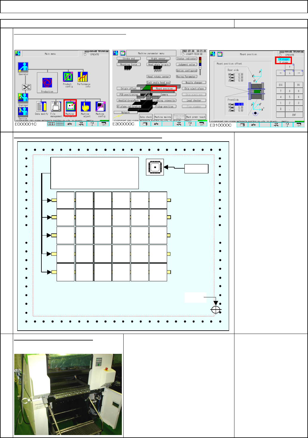
Enter "0" into the mounting position offset.
Maintenance Adjustment
3
REMARKS
Place double-sided transparent tape on the glass board
.
2
ITEM
80101122143164185
66
87
108
129
150
0
90
0
0
-90
180
90
0
-90
180
0
90
0
0
90
-90
180
0
-90
180
0
90
0
0
90
-90
180
0
-90
180
Place narrow double-sided tape.
If the viscosity of the tape is
excessively high, a glass chip
may be broken when removed.
Origin
QFP jig
EJM8A-E-SMA040307-A01-00
Page 4-3-7-3
feeder table, tightening the black screws.
Td4Z4C-a-SHA :Type A High-speed head shadow teaching
Td4Z4C-a-DIR :Type A High-speed head direct teaching
Td4Z4C-b-45D : Type B Multi-purpose head 45°teaching
Td4Z4C-b-90D : Type B Multi-purpose head 90°teaching
Td4Z4C-c-S45
: Type C High-speed shadow teaching, Multi-purpose head 45°teachin
g
Td4Z4C-c-D90
: Type C High-speed direct teaching, Multi-purpose head 90°teaching
* Type A: High-speed heads at Stages A and B
* Type B: Multi-purpose heads at Stages A and B
* Type C: High-speed head at Stage A, Multi-purpose head at Stage B
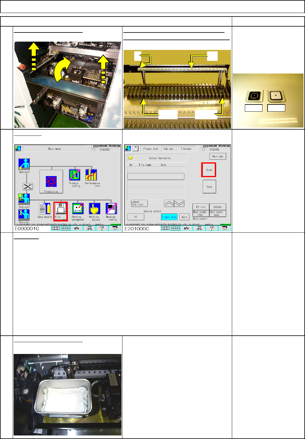
* To prevent the glass QFP jigs from
being damaged when discharged into
the NG box.
6
7
8
Place cloth in the NG box.
Data type
Load data.
REMARKS
Maintenance Adjustment
5
front and rear stages. Fix the jigs on the
Clean the QFP jigs. Place
them onto Nos. 4 to 18 of
the QFP-jig supplying jig.
Remove the feeder cover.
Place the QFP-jig supplying jig on the
Light Transfer-Head Assembly(3 nozzles)
ITEM
4 18
Slot 5 Slot 26
FrontRear
EJM8A-E-SMA040307-A01-00
Page 4-3-7-4
For details, see Section 4-3-4. "Chip
Recognition Camera Theta Axis Origin Offset"
10
11
12
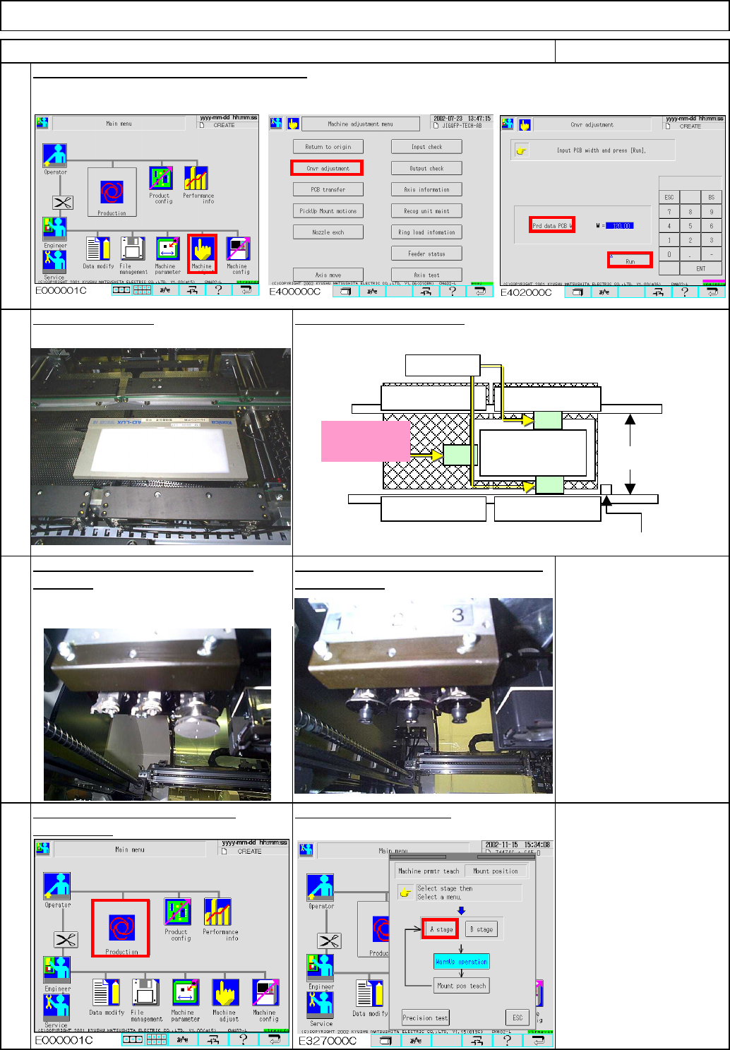
To warm up the machine, press
Fit three 1005 nozzles onto each stage:
Nozzle 1005 6 pcs.
9
Select the desired stage.
[Production].
Re-teach rotation center position to
all heads. front and rear.
Adjust the width of the conveyors manually.
Maintenance Adjustment Light Transfer-Head Assembly(3 nozzles)
ITEM REMARKS
Place the light box.
Be careful of tape position.
①
②
③
Stopper
Light Box
Middle position
Do not place
tape here!
Fixed tape
Position the light box close to the stopper.
EJM8A-E-SMA040307-A01-00
Page 4-3-7-5