CM602all_EJM8AESM_Service Manual.pdf - 第288页
If there is a table whose average is 0.005 or more correct the mounting position following the procedures below: Precision data offset Average of X-axis values……Xave Average of Y-axis values……Yave Mounting position offse…
Td4Z4C-a-SHA : Type A High-speed head shadow teaching
Td4Z4C-a-DIR : Type A High-speed head direct teaching
Td4Z4C-b-45D : Type B Multi-purpose head 45°teaching
Td4Z4C-b-90D : Type B Multi-purpose head 90°teaching
Td4Z4C-c-S45
: Type C High-speed shadow teaching, Multi-purpose head 45°teaching
Td4Z4C-c-D90
: Type C High-speed direct teaching, Multi-purpose head 90°teaching
* Type C: High-speed head at Stage A, Multi-purpose head at Stage B
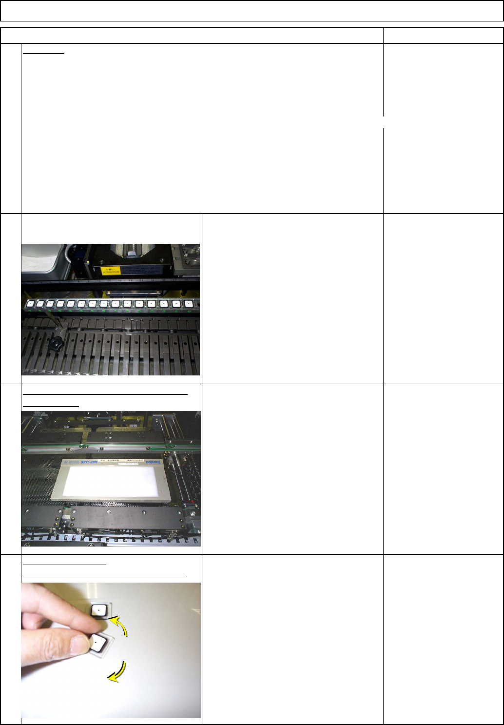
Follow Steps 11 to 33.
Remove the QFP jigs, rotating them to
avoid breaking the jigs.
Light Transfer-Head Assembly(3 nozzles)
REMARKS
34
Data type
Maintenance Adjustment
ITEM
33
35
the light box.
36
Remove the QFP jigs from the board.
Place the jigs again.
Once the teaching is finished, remove
Remove the board.
EJM8A-E-SMA040307-A01-00
Page 4-3-7-11
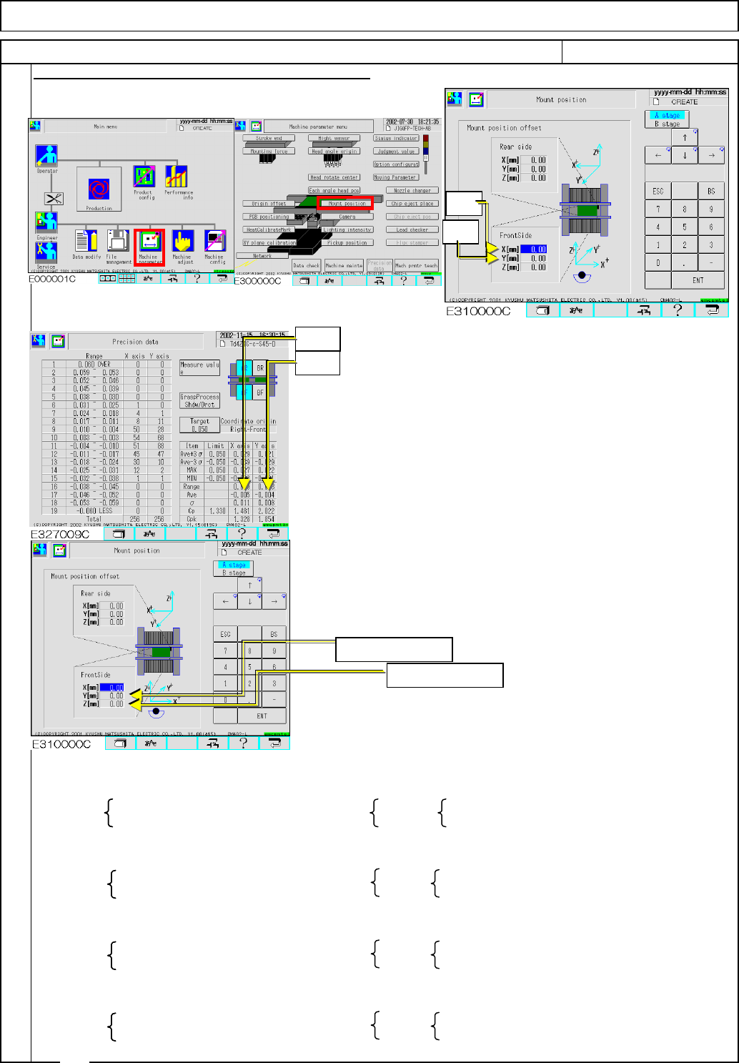
If there is a table whose average is 0.005 or more
correct the mounting position following the procedures below:
Precision data offset
Average of X-axis values……Xave
Average of Y-axis values……Yave
Mounting position offset
X(mm) value ……… Xos
Y(mm) value ………Yos
From the preset mounting position offset ([Preset Xos]
[Preset Yos]) and the average of precision data ([Xave, Yave]),
mounting position offsets to be set ([New Xos][New Yos]) are
calculated as follows:
Enter the mounting position offset ([New Xos][New Yos]).
Then follow Steps 25 to 31and check the precision data.
Right front reference
[New Xos]=[Preset Xos]+Xave [New Xos]=[Preset Xos]-Xave
[New Yos]=[Preset Yos]-Yave [New Yos]=[Preset Yos]+Yave
Left front reference
[New Xos]=[Preset Xos]-Xave [New Xos]=[Preset Xos]+Xave
[New Yos]=[Preset Yos]-Yave [New Yos]=[Preset Yos]+Yave
Right inner-side reference
[New Xos]=[Preset Xos]+Xave [New Xos]=[Preset Xos]-Xave
[New Yos]=[Preset Yos]+Yave [New Yos]=[Preset Yos]-Yave
Left inner-side reference
[New Xos]=[Preset Xos]-Xave [New Xos]=[Preset Xos]+Xave
[New Yos]=[Preset Yos]+Yave [New Yos]=[Preset Yos]-Yave
Procedures for Entering the Mounting Position Offset
Front Rear
Front Rear
37
Rear
Front Rear
Light Transfer-Head Assembly(3 nozzles)
Front
Maintenance Adjustment
ITEM REMARKS
Xave
Yave
Xos
Yos
Enter new Xos.
Enter new Yos.
EJM8A-E-SMA040307-A01-00
Page 4-3-7-12
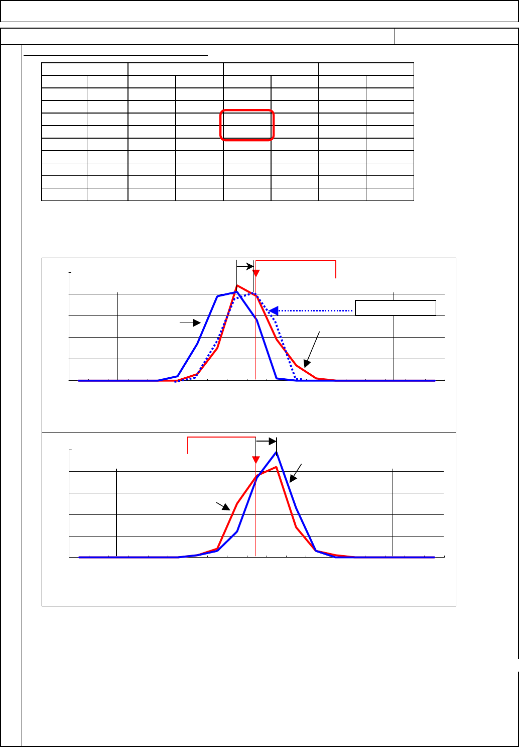
Three types of data (Front, Rear, Front and Rear Total) are shown in the precision data.
The reason that the X-axis Cpk value of Front and Rear Total drops slightly even though the value
of each side (front and rear) is appropriate is that there is a large difference between the maximum
and the minimum of the rear X-axis (Ideal difference: 0). (Opposite sign) See the graphs below:
1
2
3
4
5
6
7
8
9
10
11
12
13
14
15
16
17
18
19
Fig.38-2(1) correction
From data Difference of Min. and Max./2=(0.027+0.004)/2=0.015
(fig40-1) 0.015-0.027=-0.012
Enter -0.012 into the rear X-axis mounting position offset so that the Cpk will become similar
to the dotted line on Graph (1) (Correction target).
For the Y-axis: Although the graph is shifted to the negative side by 0.010 (fug40-3(2)), the FY
and the RY are so balanced that the Cpk does not drop.
It is recommended that the front offset be 0 (*); enter the rear offset only.
If the average exceeds 0.005, carry out Adjustment Step 37. In this case, enter an offset.
* Enter "0" into the front offset and adjust with the rear offset so that the Cpk will become the target value.
Procedures for Entering the Mounting Po
s
Maintenance Adjustment Light Transfer-Head Assembly(3 nozzles)
範囲
RX軸 RY軸 SX軸
前側 後側 前後合計
FX軸 FY軸 SY軸
0000
0000
000
00
000
0
316
0001
0
20 91
023737
149
85 37
28 37 67 75
41 12
20 2
39 3 54 7
17 1
00
2020
00
0
0000
00
0
00
0000
00
0
0
25
38
42
14
0
3
1
0
0
0
1
4
0
0
0
0
0
0
0
0
39
19
7
1
0.003 ~ -0.003
-0.004 ~ -0.010
0
0
0
0
0
3
15
44
38
0
0
0
0.038 ~ 0.032
0.031 ~ 0.025
0.024 ~ 0.018
-0.039 ~ -0.045
0.045 ~ 0.039
ITEM REMARKS
0
-0.060 LESS
0
0
-0.025 ~ -0.031
-0.032 ~ -0.038
-0.011 ~ -0.017
-0.046 ~ -0.052
0.017 ~ 0.011
0.010 ~ 0.004
0-0.053 ~ -0.059
0.060 OVER
0.059 ~ 0.053
0.052 ~ 0.046
-0.018 ~ -0.024
0
10
20
30
40
50
0.060 OVER
0.059 ~
0.053
0.052 ~
0.046
0.045 ~
0.039
0.038 ~
0.032
0.031 ~
0.025
0.024 ~
0.018
0.017 ~
0.011
0.010 ~
0.004
0.003 ~ -
0.003
-0.004 ~ -
0.010
-0.011 ~ -
0.017
-0.018 ~ -
0.024
-0.025 ~ -
0.031
-0.032 ~ -
0.038
-0.039 ~ -
0.045
-0.046 ~ -
0.052
-0.053 ~ -
0.059
-0.060 LESS
0
10
20
30
40
50
0.060 OVER
0.059 ~
0.053
0.052 ~
0.046
0.045 ~
0.039
0.038 ~
0.032
0.031 ~
0.025
0.024 ~
0.018
0.017 ~
0.011
0.010 ~
0.004
0.003 ~ -
0.003
-0.004 ~ -
0.010
-0.011 ~ -
0.017
-0.018 ~ -
0.024
-0.025 ~ -
0.031
-0.032 ~ -
0.038
-0.039 ~ -
0.045
-0.046 ~ -
0.052
-0.053 ~ -
0.059
-0.060 LESS
0point
FX
RX
FY
RY
0point
-0.0500.050
-0.0500.050
Fig.38-2
Fig.38-3
(1)
(2)
X-axis graph
Correction target
Y-axis graph
0.050
Tolerance
1959
-0.050
0.050
-0.050
1.330
0.027
-0.021
0.021
-0.018
0.040
0.003
0.008
2.091
FX-axis
2.059
0.020
-0.026
0.019
-0.025
0.044
-0.003
0.008
2.152
FY-axis
Front
1.708
0.032
-0.019
0.027
-0.018
0.046
0.007
0.008
1.976
SX-axis
2.078
0.020
-0.026
0.019
-0.025
0.044
-0.003
0.008
2.213
SY-axis
Front & Rear Total
1.819
0.032
-0.011
0.027
-0.004
0.032
0.010
0.007
2.299
RX-axis
2.124
0.018
-0.026
0.019
-0.021
0.040
-0.004
0.007
2.307
RY-axis
Rear
A
ve+3σ
A
ve-3σ
MAX
MIN
Range
Ave
σ
Cp
Cpk
Item
Fig.38-1
EJM8A-E-SMA040307-A01-00
Page 4-3-7-13