CM602all_EJM8AESM_Service Manual.pdf - 第349页
I Since this adjustment requires releasing the safety cover switch, only those who are authorized to release it based on the Document "Key Switch/Key Disk Receipt Confirmation and Safety Precautions" are permit…
13
Put the feeder cover back on.
Item Remarks
Machine Part Replacement Main Body
EJM8A-E-SMA050106-A01-00
Page 5-1-6-5
I Since this adjustment requires releasing the safety cover switch, only those who are
authorized to release it based on the Document "Key Switch/Key Disk Receipt
Confirmation and Safety Precautions" are permitted to perform this adjustment.
Main Body
5-1-7 Y-axis Secondary-Part Replacement
Machinery Part Replacement
Min.60 Min.
kg
Assembly/Adjustment
Teaching
120
Min.60 Min.
• This section describes the procedures for replacing the Y-axis secondary-part.
Total Time Part Weight
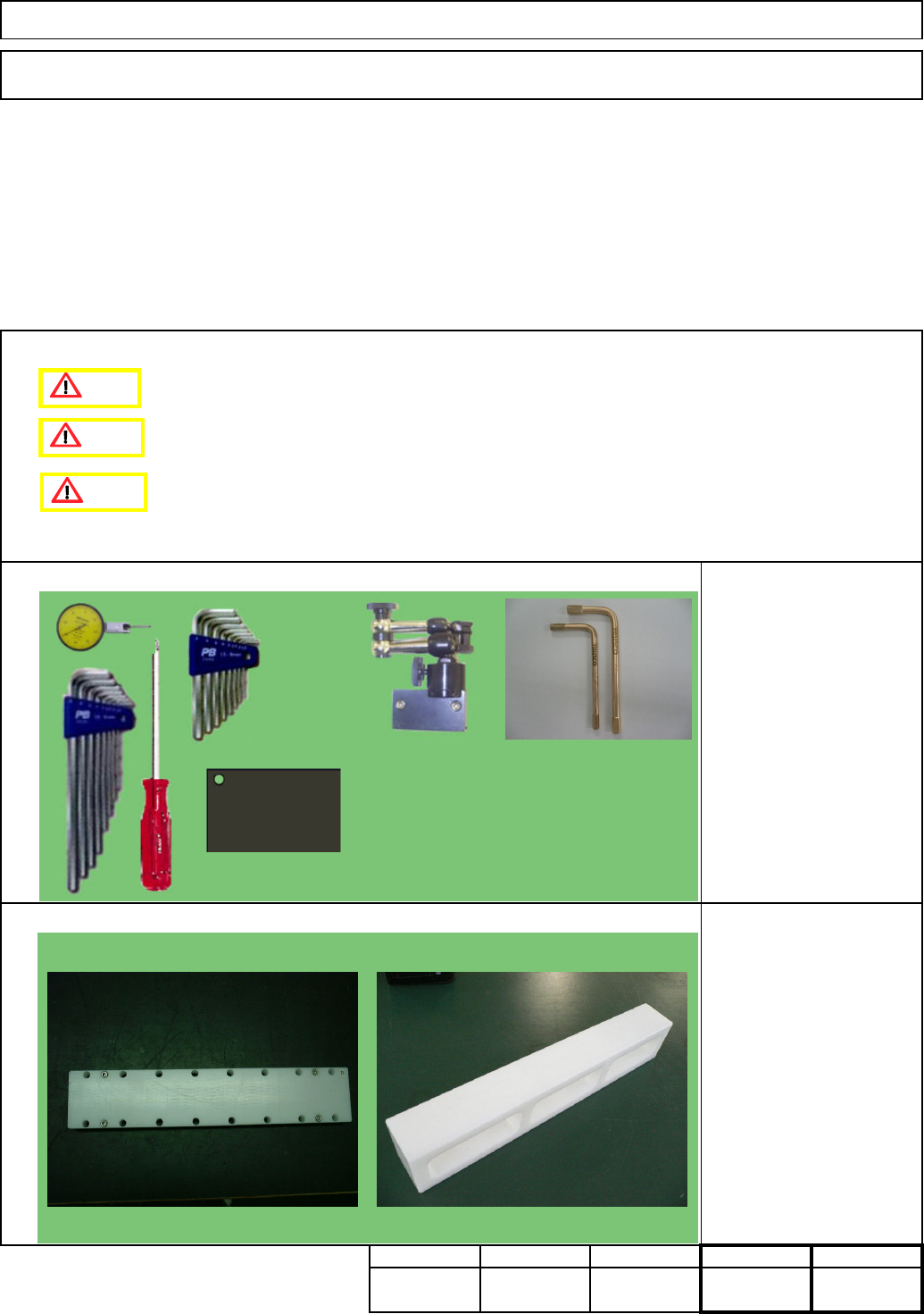
Cover jigs
Y-axis secondary-part
installing jig
Tools
Jig
Phillips screwdriver #2
Allen keys 3 - 5mm
Magnetic stand
Stand-mounting iron plate
Dial gauge
Short wrench
Non-magnetic Allen key
Removal/Disassembly
Caution
Danger
Warning
Non-magnetic Allen key (Straight)
Should be short-processed.)
Picture: Manufacturer: TRUSCO
NAKAYAMA
Flame-proof tool series
Model: BHX-4, BHX-5 (Size M4 and M5)
EJM8A-E-SMA050107-A01-00 Page 5-1-7-1
Replacement stage AF
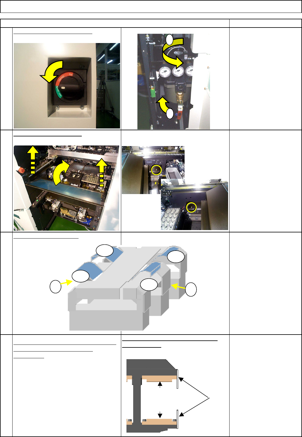
Turn off the power and the air.
2
Machine Part Replacement Main Body
1
Item
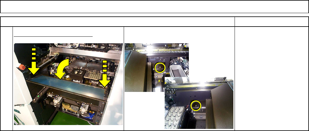
Remove the feeder cover.
Remove the side covers.
Allen key 3 mm
Screw M4 (Special) x 2
Remarks
3
4
Move the beam from the replacement stage
so that it will not interfere with the
replacement.
Remove the covers from the sides of the
secondary parts.
Move the AF and AR
beams to the end of the
AR Y-axis.
1
2
AF
BR
AR
BF
1
2
Cover
Center frame
Upper secondary part
Lower secondary part
EJM8A-E-SMA050107-A01-00 Page 5-1-7-2