CM602all_EJM8AESM_Service Manual.pdf - 第354页
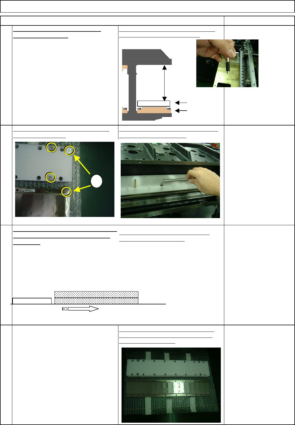
* Do not confuse the poles. Install the secondary part so that the "N" mark is positioned outward. Machine Part Replacement 20 The same poles repel each other. 18 19 Secondary-parts mounted Referring to the rea…
Remove the bolts from the cover jig.
Remove the upper secondary part (2),
repeating Steps 7 to 12.
To remove the lower secondary parts, use a short
wrench because working space is limited.
Put the cover over the secondary part (3),
aligning the "N" marks.
Tighten the four cover bolts. Loosen the 18
secondary-part holding bolts.
The secondary parts (3) and (4) are attracted
with magnetism. Separate them by sliding
the part (3).
Remove the secondary part (3) and the
cover from the center frame.
Leave secondary-part storing place
beforehand. Do not put a magnetic
material close to the part.
Before removing the cover from the part,
prepare a substitute cover (non-
magnetic).
Main Body
16
Remove the cover from the secondary part. (That
cover will be used for the Upper Part (4)) * Put a
substitute cover immediately.
Machine Part Replacement
Item Remarks
Non-magnetic Allen key
(M4)
Short-processed
For tightening lightly
Not for securely.
14
13
Loosen the bolts that were securely
tightened with a non-magnetic
Allen key. Do not securely tighten.
(The Allen key is Not sufficiently
strong.)
15
Center frame
Lower
secondary part
Cover
Working
space
N
Cover
Secondary
part
Secondary
part (4)
Secondary part (3)
Cover
EJM8A-E-SMA050107-A01-00 Page 5-1-7-5
* Do not confuse the poles.
Install the secondary part so that the "N" mark is positioned outward.
Machine Part Replacement
20
The same poles repel each other.
18
19
Secondary-parts mounted
Referring to the rear-secondary-part
position, mount the front parts in the
order shown below
17
They have magnetic poles: N and S.
Main Body
Item Remarks
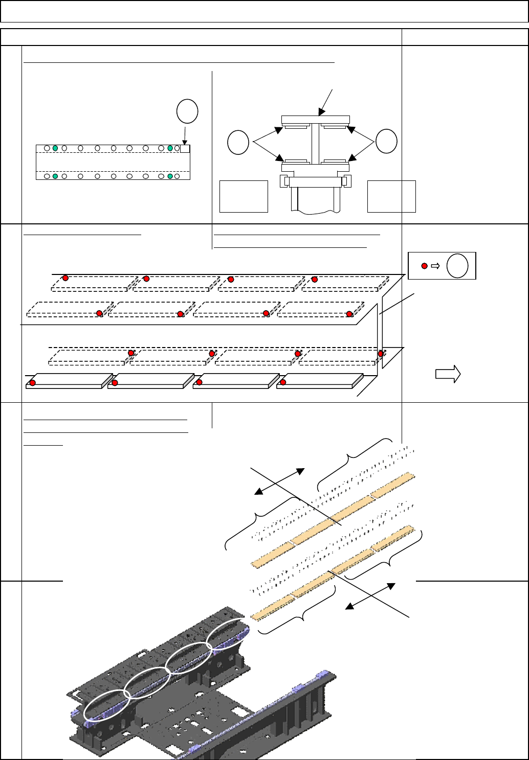
Stage A
Stage B
Center
f
Operator's
side
N
N
N
Center frame
Stage A Stage B
Seen from the operator's side
N
N
Lower rear
secondary-part
Lower front
secondary-part
Upper front
secondary-part
Upper rear
secondary-part
(1)
(2)
(3)
(4)
EJM8A-E-SMA050107-A01-00 Page 5-1-7-6
Tighten the four cover bolts.
Tighten the four cover bolts.
22
23
24
Mount the part (2), following the same
procedures.
See No.17.
Put the cover over the secondary part (1),
aligning the "N" marks.
A
lign the upper secondary part
(
3
)
, the cover with t
h
secondary-part installing jig. Mount them on the part
(1). Create the gap between the rear part and the part
(
3
)
.
Machine Part Replacement Main Body
Item Remarks
Put the cover over the secondary part (1),
aligning the "N" marks.
21
Ch
ec
k
t
h
e part
(1)
w
i
t
h
t
h
e cover
f
or
orientation. Create the gap between the rear
part and the part (1). Mount the part (1) on
the center frame.
Slide the part (1) until it makes a contact
with the rear part.
Tighten the 18 secondary-part holding bolts.
Loosen the four cover bolts and remove the
cover.
Slide the part (3) until it makes contact with the rear
part. Tighten the 18 secondary-part holding bolts.
Loosen the four cover bolts and remove the cover.
Mount the part (4), following the same
procedures.
See Nos. 23 and 24.
N
N
N
Cover
Secondary
part
Rear
secondar
y
p
ar
t
Secondary
p
art
(
1
)
N
N
N
Cover
Secondary
part
Rear
secondary
t
Cover
Upper secondary part (3)
Secondary-part
installing jig
Secondary part (1)
EJM8A-E-SMA050107-A01-00 Page 5-1-7-7