CM602all_EJM8AESM_Service Manual.pdf - 第361页
13 After assembly, check the gap between the frame and the secondary part. Gap: 15 - 15.5 mm Item Remarks 14 Referring to "Y-axis Secondary-Part Replacement," mount the secondary parts. Secure the cables with a…
Be careful of magnetism when working on the parts.
10
11
Item
Main Body
Remarks
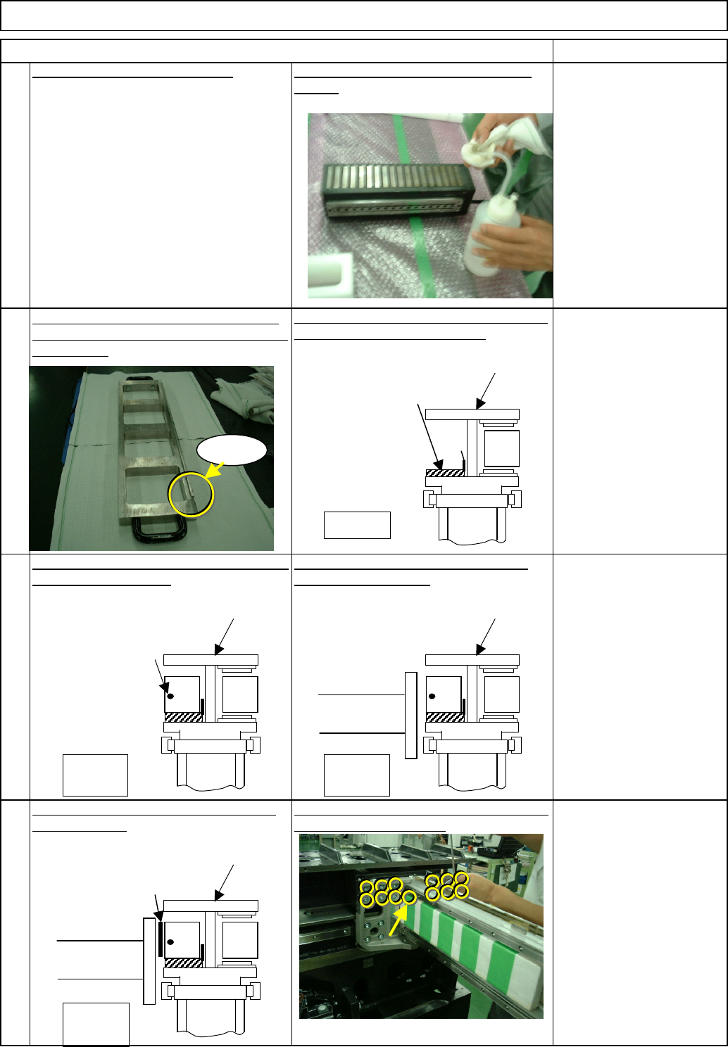
Mount the Y-axis primary-part-slide stand on
the center frame as shown below.
Mount the primary part on the stand, aligning
the part with the convex.
Move the beam towards you to position it
next to the primary part.
Position the Y-axis primary-part-slide stand
so that the convex comes to the center of the
center frame.
9
With the brown plate in, lightly tighten the 13
primary-side holding bolts.
Machine Part Replacement
12
Use a non-magnetic Allen
key (M5).
Put the brown plate between the beam and
the primary part.
Clean the new primary part with cloth and
alcohol.
Move the beam to the rear side.
Center frame
Stage A
When seen from operator
Y-axis primary-part-slide
stand
Convex
Convex
Stage
A
The cable position
should be at left.
Stage
A
Beam
Stage A
Beam
Brown plate
When seen from operator
Center frame
Center frame
When seen from operator
Center frame
When seen from operator
EJM8A-E-SMA050108-A01-00
Page 5-1-8-4
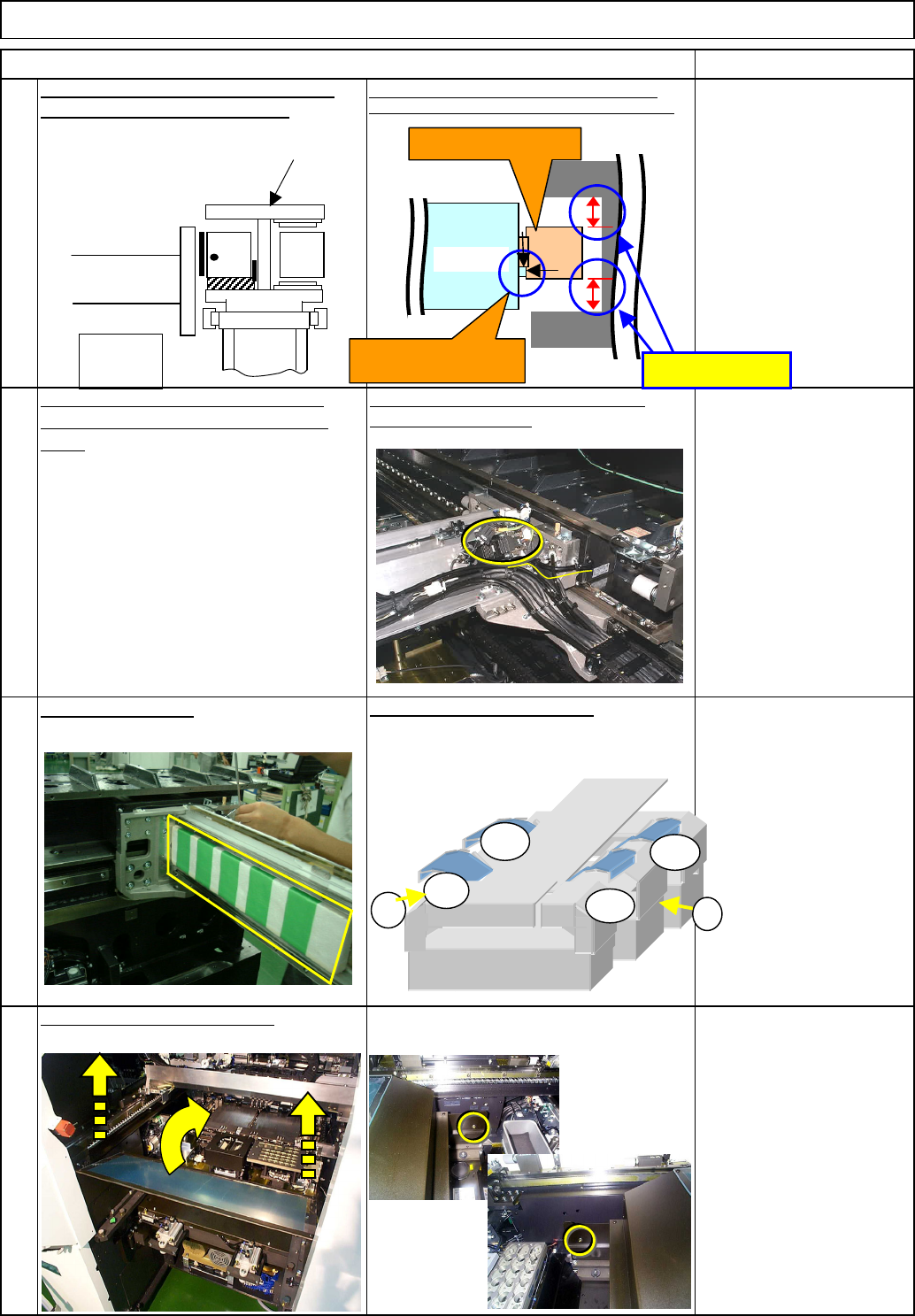
13
After assembly, check the
gap between the frame
and the secondary part.
Gap: 15 - 15.5 mm
Item Remarks
14
Referring to "Y-axis Secondary-Part
Replacement," mount the secondary
parts.
Secure the cables with a cable tie, and
connect the connector.
Put the feeder cover back on.
Machine Part Replacement
15
Remove the cover.
Put the side covers back on.
Wrench 3 mm
Screw M4 (Special) 2 pcs.
16
Main Body
Holding the handle of the Y-axis primary-
part-slide stand, pull the stand out.
Pressing the primary part against the machined side,
tighten the upper bolts and then lower one. (See below.)
Stage A
Beam
A
F
BR
A
BF
1
2
Y-axis primary part
15 - 15.5 mm
X-axis
Press the part against the
machined side.
Center frame
When seen from operator
EJM8A-E-SMA050108-A01-00
Page 5-1-8-5
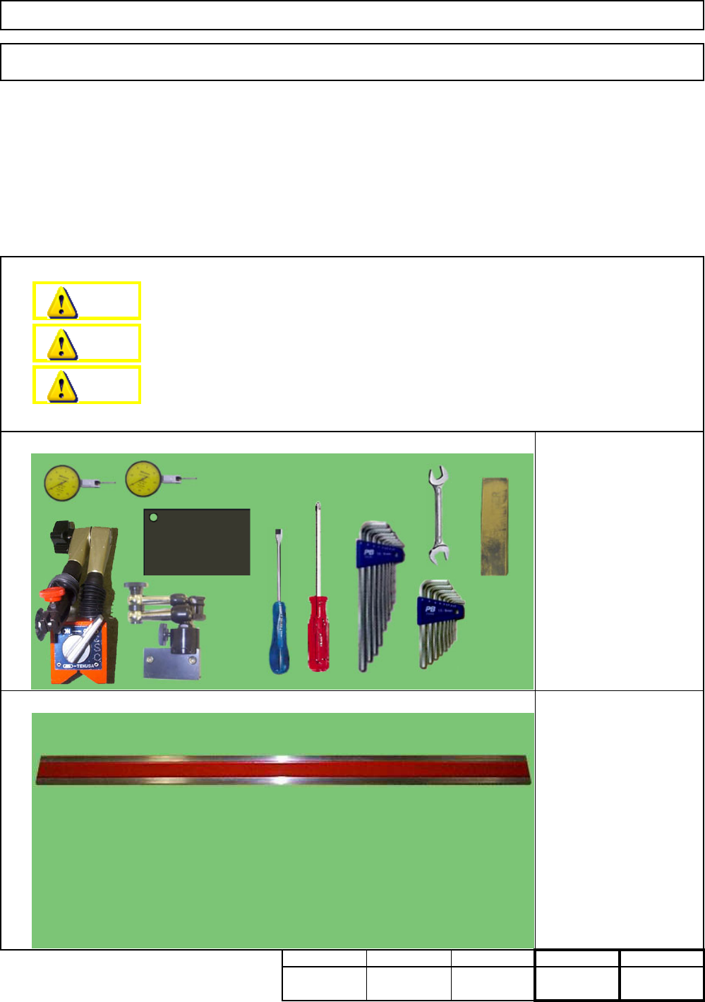
Tools
Jigs
5-1-9 X-axis Linear Rail Replacement
Main BodyMachine Part Replacement
This section describes the procedures for replacing the X-axis linear rails.
Total Time Part Weight
10
Assembly/AdjustmentRemoval/Disassembly
120
Straight edge 1500 mm
Block gauge 35 mm
Block gauge 85 mm
Min.
6040
Phillips screwdriver #2
Slotted screwdriver #1
Allen key 3 mm
Allen key 4 mm
Wrench 7 mm
Magnetic stand
Dial gauge
Iron plate
Oil stone
Cloth
Teaching
Min. Min. kgs.
220
Min.
Dange
r
Warning
Caution
EJM8A-E-SMA050109-A01-00
Page 5-1-9-1