CM602all_EJM8AESM_Service Manual.pdf - 第375页
4-2-2 "Board Recognition Camera --- X and Y-axis Origin Offset" 4-2-3 "Z-axis Origin Offset" 4-2-4 "Chip Recognition Camera - Theta-axis Origin Offset" 4-2-5 "Determining the Mounting H…
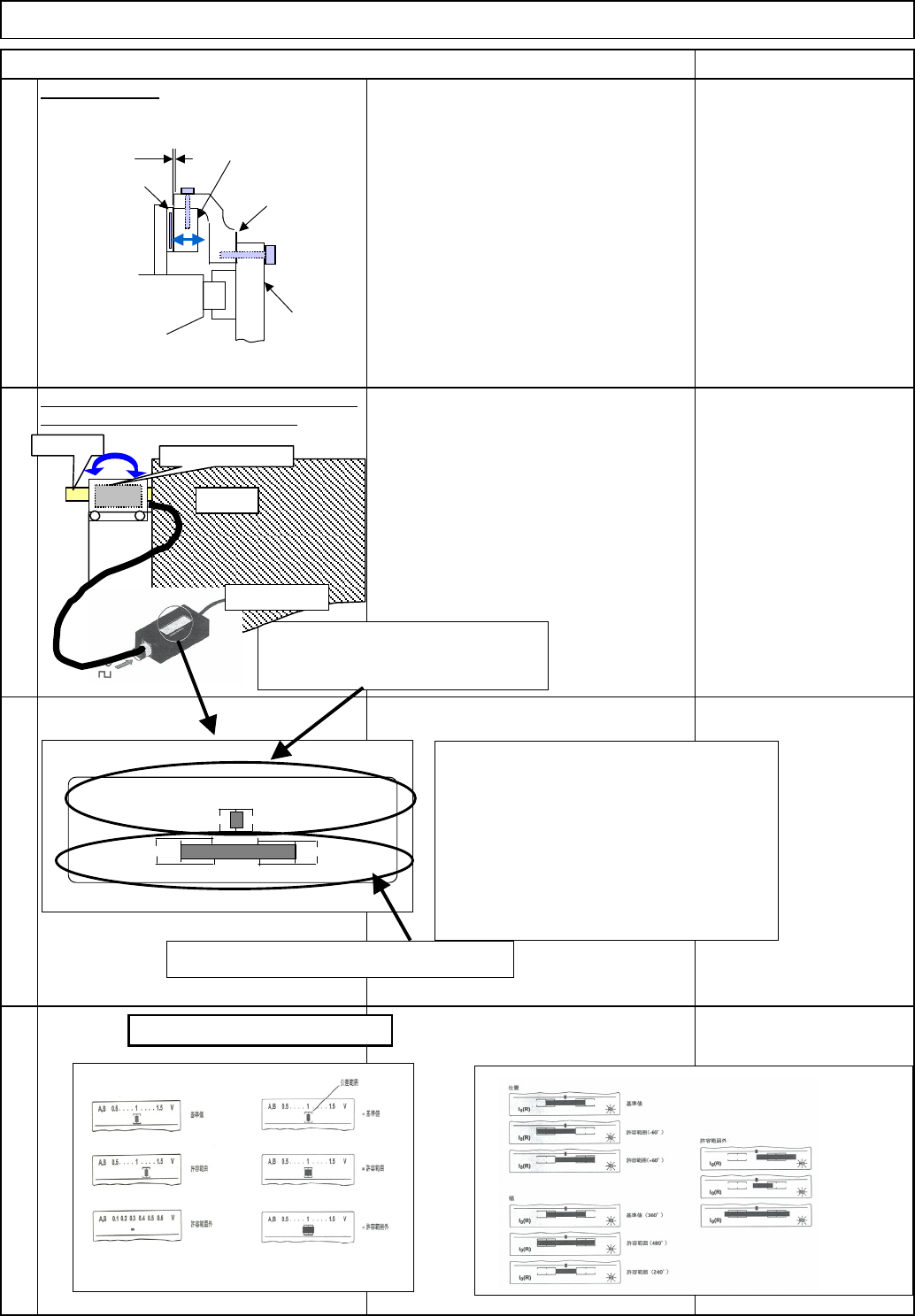
Adjust the gap.
The size and the quality of the incremental signal are
displayed. Check them at the entire stroke.
Item Remarks
Main Body
9
12
Machine Part Replacement
10
11
Head plate
Bracket
Encoder head
Scale holder
0.15
Connect the adjustment jig PWT18 to
the encoder. Check that the
incremental signal and the reference
mark signal satisfy
the range.
A、B 0.5 . . . . 1 . . . .
15
V
l0(R)
RI
[Reading]
The size and the quality of the
incremental signal are displayed.
Check them at the entire stroke.
X
Quality of incremental
signal
Size of incremental
signal
X
o
Quality of reference-
mark signal
1. Over the entire stroke of the
incremental signal:
size: 0.8 V or more
Quality: The bar should be in the frame.
2. Reference mark signal
Quality: The left and right ends of the bar
should be in the frames.
[Criteria]
Main bod
y
of PWT18
Size and quality of the reference mark
Adjust the bracket with the special shim
until the gap between the encoder head
and the scale is 0.15 mm
Head
Encoder head
Scale
Power 100V
PWT18
o
o
o
o
o
o
o
X
X
X
EJM8A-E-SMA050111-A01-00
Page 5-1-11-4
4-2-2 "Board Recognition Camera --- X and Y-axis
Origin Offset"
4-2-3 "Z-axis Origin Offset"
4-2-4 "Chip Recognition Camera - Theta-axis Origin
Offset"
4-2-5 "Determining the Mounting Height and
Positioning the Board"
4-2-6 "XY Plane Calibration"
4-2-8 "Pickup position"
4-2-9 "Nozzle Exchange Position"
4-2-10 "Light Intensity"
4-2-7 "Mounting Position"
4-3-2 "Board Recognition Camera --- X and Y-axis
Origin Offset"
4-3-3 "Z-axis Origin Offset"
4-3-4 "Chip Recognition Camera --- Theta Axis
Origin Offset"
4-3-5 "Determining the Mounting Height and
Positioning the Board"
4-3-6 "XY Plane Calibration"
4-3-8 "Pickup Position"
4-3-9 "Nozzle Exchange Position"
403-10 "Load Head"
4-3-11 "Lead Checker"
4-3-12 ""Light Intensity"
4-3-7 "Mounting Position"
Teaching
Machine Part Replacement Main Body
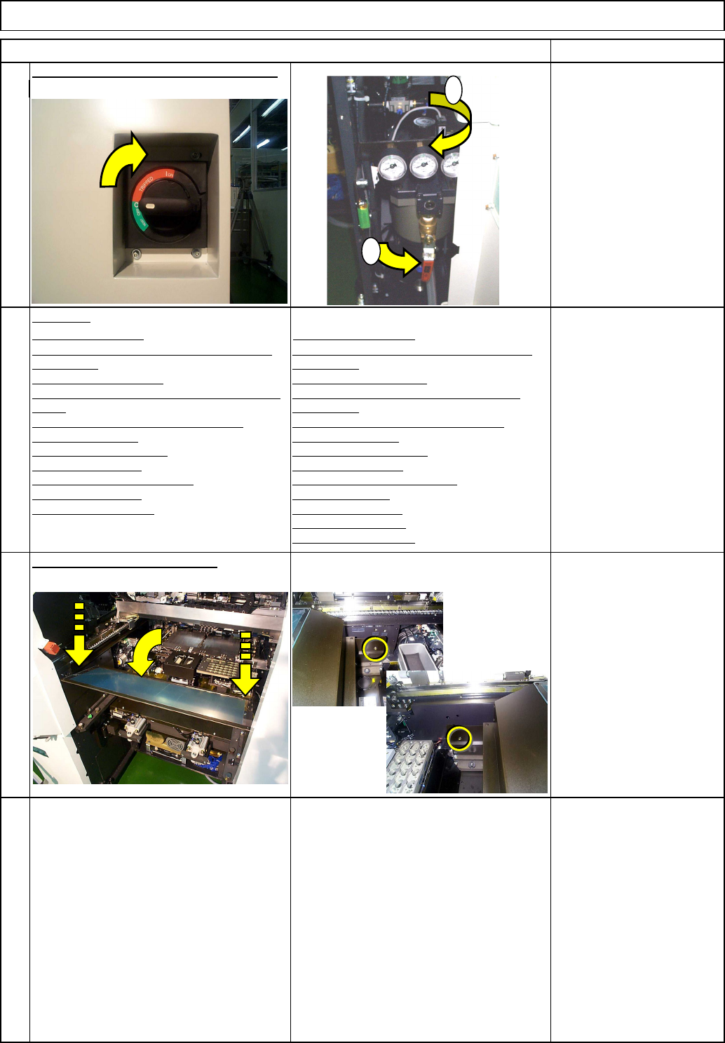
From 0.49MPa
to 0.54MPa
Put the feeder cover back on.
Item Remarks
13
Switch on the power and the air supply.
15
14
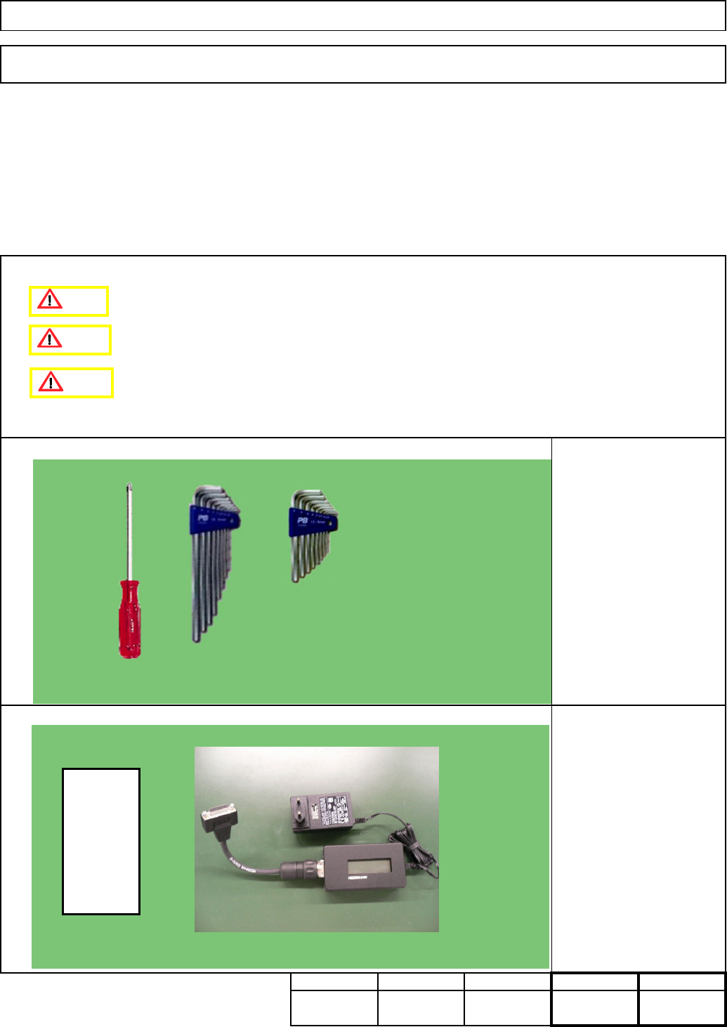
Phillips screwdriver #2
Screw M4 2 pcs.
High-Speed Head
Multi-purpose Head
1
2
EJM8A-E-SMA050111-A01-00
Page 5-1-11-5
45 Min. Min.
Special shim (0.15 mm)
Linear-scale adjustment jig
PWT18
Phillips screwdriver #2
Allen keys 3 mm
Allen keys 4 mm
Cloth
Teaching
Tools
Jig
Min.70
kg
235
Assembly/AdjustmentRemoval/Disassembly
120 Min.
5-1-12 Y-axis Linear Scale Replacement
Main BodyMachinery Part Replacement
• This section describes the procedures for replacing the Y-axis linear scale.
Total Time Part Weight
0.15mm
32.0
75.0
Caution
Danger
Warning
EJM8A-E-SMA050112-A01-00
Page 5-1-12-1