CM602all_EJM8AESM_Service Manual.pdf - 第38页
CM602- L Se r vi c e Manual 36 Safety sw itches Sa fe ty sw itch on th e sa fety cov er Bef or e starti ng regul ar autom a tic producti on on the m a chi ne, close all sa f ety cov ers. Si nce a screen di splays the m…
CM602-L
Service Manual
35
EJK1A-013E
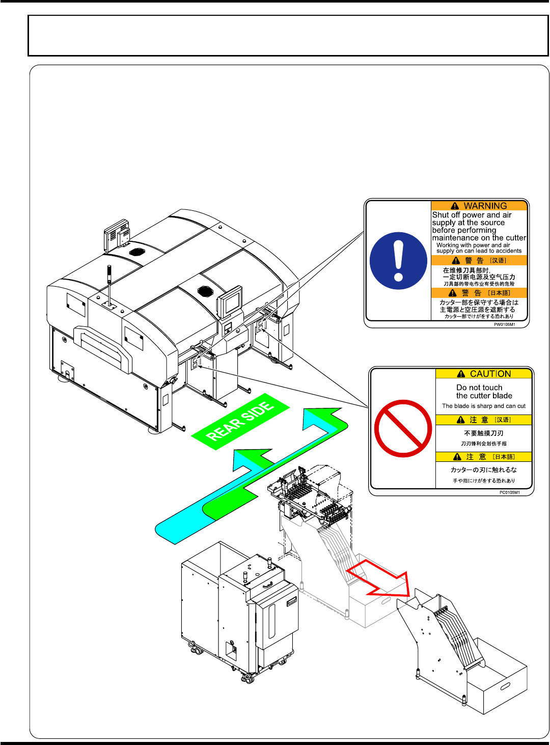
Labels pasted on product for safety
Direct tray type (Option)
Warning labels / Caution labels
The warning labels are pasted on this machine as follows. Follow the instructions on each label.
If it has come off, place an order with us for it, referring to its label No. in the Parts List; then, put the new
one on the proper location.
Warning label locations for direct tray type
The warning/caution labels are affixed only to the stage where the direct tray feeder and the 6-row feeder
mount are to be connected. Therefore the stages where the labels are affixed vary depending on your
specifications. (The direct tray feeder and the 6-row feeder mount can be connected only to the rear side
of CM602-L.)
EJM8A-E-XXA00-A04-00
CM602-L
Service Manual
36
Safety switches
Safety switch on the safety cover
Before starting regular automatic production on the machine, close all safety covers.
Since a screen displays the message prompting you to supply a material when necessary, open the
corresponding cover according to the target material and then conduct the work.
If you accidentally open a safety cover during automatic production, the machine comes to an
emergency stop to ensure the safety of operators.
(
“Safety precautions”)
Servo switch
Since an operator needs to put the hands or part of body into the machine for changeover or
maintenance, the operating panel is equipped with the servo switch in order to ensure on-the-job
safety. When the servo switch is turned OFF (O), all of the drive shafts of the machine will be inactive.
(
Operation Manual, “1.1 Operating Panel”)
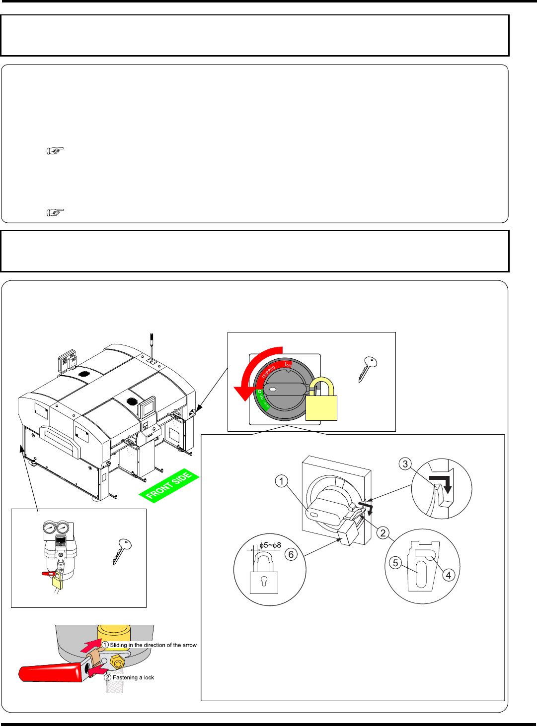
Lock out tagout procedure
Lock out tag out for each maintenance is required. It is described as “Turn OFF the power and air.” in
each manual. We recommend that the key be under control of the trained engineer in accordance with
your control standards.
Power supply switch
Key
4Z4C-824E
How to keep the power supply switch under lock and key
EJM4A-AA01
Main air valve
Key
EJM4A-132E
4Z4C-824E
4Z4C-027E
1 Turning the handle
of the power supply switch to RESET, pull
out the lock plate
in the direction of the arrow, and then hook
it on the rib
.
∗
The handle can be locked only when it is located in the OFF
position.
2
Put a lock (
φ
5 to
φ
8)
into the lock plate
hole
.
How to keep the air valve under lock and key
∗
Avoid putting a lock into the lock plate hole
.
4Z4C-J-XXB00-A04-00
EJM8A-E-XXA00-A04-00
CM602-L
Service Manual
37
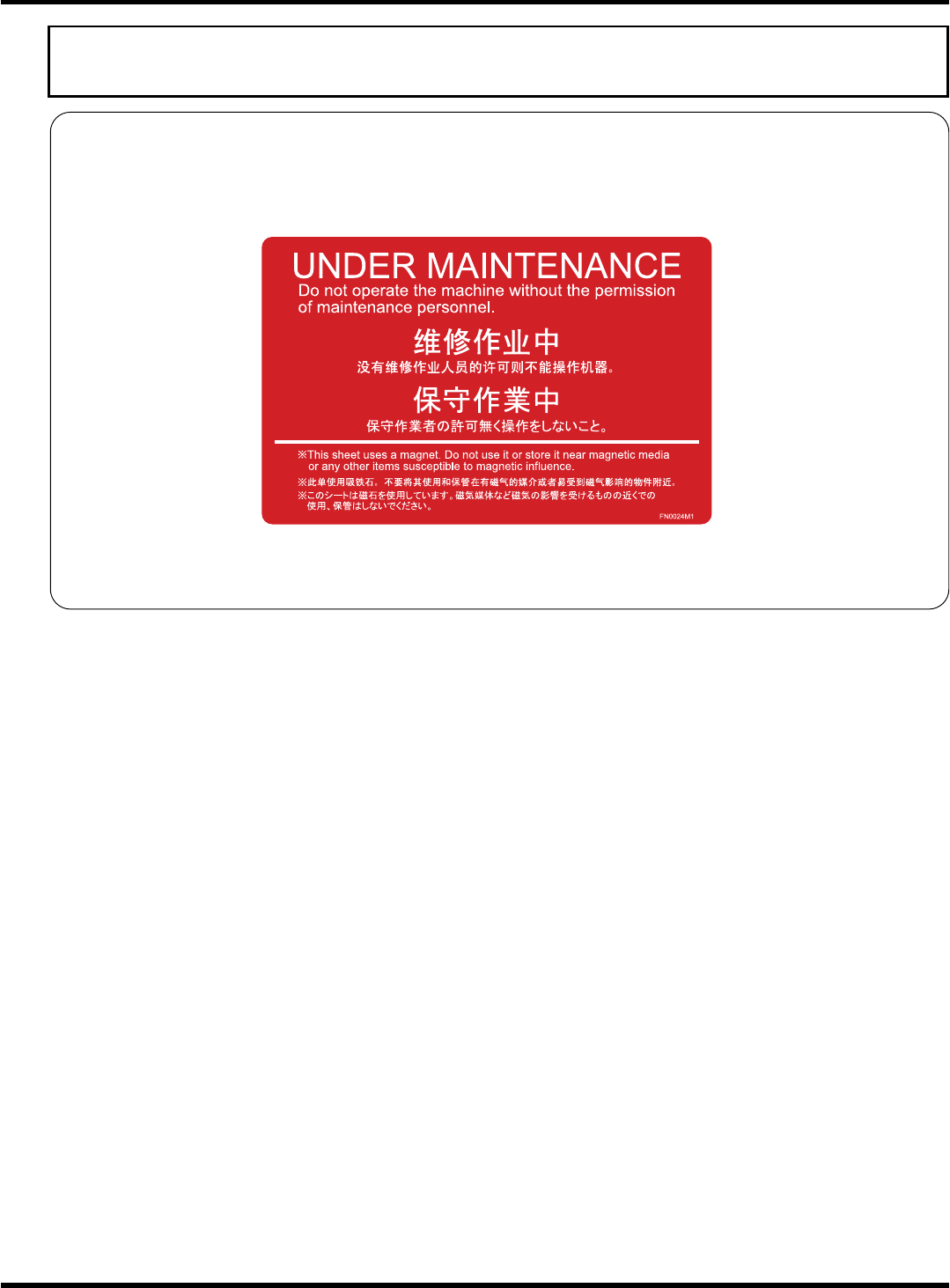
Usage of warning sheets in maintenance
Before performing maintenance, affix the included warning sheets (see below) to prominent positions,
such as the operating panel or the vicinity of it, for safety.
During the maintenance by two or more persons in particular, as well as using these warning sheets to
ensure safety, be sure to send signals.
This warning sheet uses a magnet. Do not use it or store it near magnetic media or any other items
susceptible to magnetic influence.
EJM8A-E-XXA00-A04-00