CM602all_EJM8AESM_Service Manual.pdf - 第380页
Teaching Item Remarks 13 Switch on the power and the air supply. From 0.49MPa to 0.54MPa High-Speed Head Multi-purpose Head 4-2-2 "Board Recognition Camera --- X and Y-axis Origin Offset" 4-2-3 "Z-axis Ori…
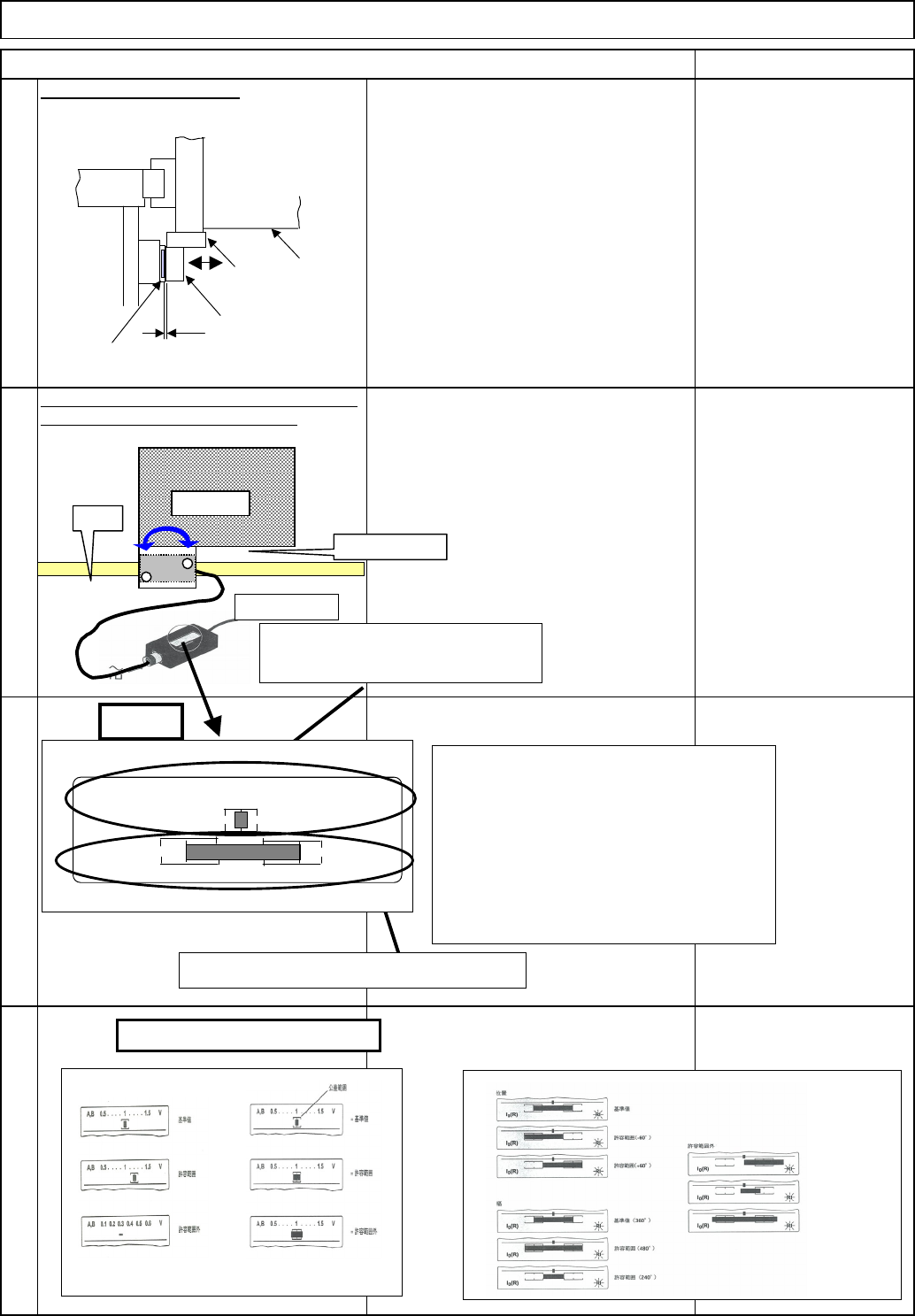
Adjust the gap to 15 mm.
Item Remarks
9
11
12
Machine Part Replacement Main Body
The size and the quality of the incremental signal are
displayed. Check them at the entire stroke.
10
調整治具PWT18をエンコーダヘッドに
接続し、インクリメンタル信号、参照
マーク信号が許容範囲内に入っている
ことを確認する。
The size and the quality of the
incremental signal are displayed.
Check them at the entire stroke.
Encoder head
Scale
Power
PWT18
X beam
Encoder head
Scale holder
0.15
Bracket
X beam
Adjust the bracket with the special shim
until the gap between the encoder head
and the scale is 0.15 mm
[Criteria]
1. Over the entire stroke of the
incremental signal:
size: 0.8 V or more
Quality: The bar should be in the frame.
2. Reference mark signal
Quality: The left and right ends of the bar
should be in the frames.
Size and quality of the reference mark
A、B 0.5 . . . . 1 . . . .
15
V
l0(R)
RI
[Reading]
X
Quality of incremental
signal
Size of incremental
signal
X
o
Quality of reference-
mark signal
Main bod
y
of PWT18
o
o
o
o
o
o
o
X
X
X
EJM8A-E-SMA050112-A01-00
Page 5-1-12-4
Teaching
Item Remarks
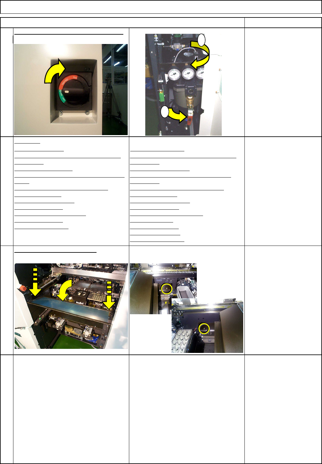
13
Switch on the power and the air supply.
From 0.49MPa
to 0.54MPa
High-Speed Head
Multi-purpose Head
4-2-2 "Board Recognition Camera --- X and Y-axis
Origin Offset"
4-2-3 "Z-axis Origin Offset"
4-2-4 "Chip Recognition Camera - Theta-axis Origin
Offset"
4-2-5 "Determining the Mounting Height and
Positioning the Board"
4-2-6 "XY Plane Calibration"
4-2-8 "Pickup position"
4-2-9 "Nozzle Exchange Position"
4-2-10 "Light Intensity"
4-2-7 "Mounting Position"
4-3-2 "Board Recognition Camera --- X and Y-axis
Origin Offset"
4-3-3 "Z-axis Origin Offset"
4-3-4 "Chip Recognition Camera --- Theta Axis
Origin Offset"
4-3-5 "Determining the Mounting Height and
Positioning the Board"
4-3-6 "XY Plane Calibration"
4-3-8 "Pickup Position"
4-3-9 "Nozzle Exchange Position"
403-10 "Load Head"
4-3-11 "Lead Checker"
4-3-12 ""Light Intensity"
4-3-7 "Mounting Position"
15
Phillips screwdriver #2
Screw M4 2 pcs.
Put the feeder cover back on.
14
Machine Part Replacement Main Body
1
2
EJM8A-E-SMA050112-A01-00
Page 5-1-12-5
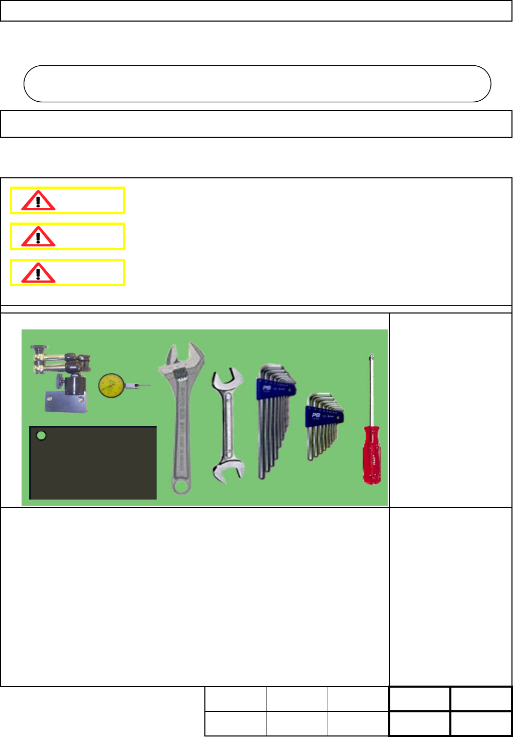
This section describes the procedures for replacing the support plate cylinder.
Phillips screwdriver #2
Allen key 2.5 mm
Allen key 3 mm
Allen key 4 mm
Allen key 5 mm
Wrench 30 mm
Box wrench 30 mm
Dial gauge
Iron plate
Magnetic stand
None
5-2-1 Support Plate Cylinder Replacement
Machinery Part Replacement Board Holder Unit
・Tools
・Jig
30 min. min.
min
.
30
Kgs
.
Removal
Disassembly
A
ssembl
y
Adjustment
Teaching Total Time
Weigh
t
o
f
Part
30 min.
60
Board Holder Unit
5-2
Dange
r
Warning
Caution
EJM8A-E-SMA050201-A01-00
Page 5-2-1-1