CM602all_EJM8AESM_Service Manual.pdf - 第387页
Tighten screws holding the support-plate upper-limit determining bars. 21 Remove the bar from the support-plate upper-limit determining bar 24 Remove the block. Tools and Specifications Allen key 5mm Screw M3 6 pcs. Tool…
joint.
and the dog, which are moved in Step 8.
100-mm block or
equivalent
Item Remark
Machinery Part Replacement Board Holder Unit
17
Place the support table in the machine.
Tools and Specifications
・Be careful not to damage the cylinder
・Be careful of interference of the sensor
18
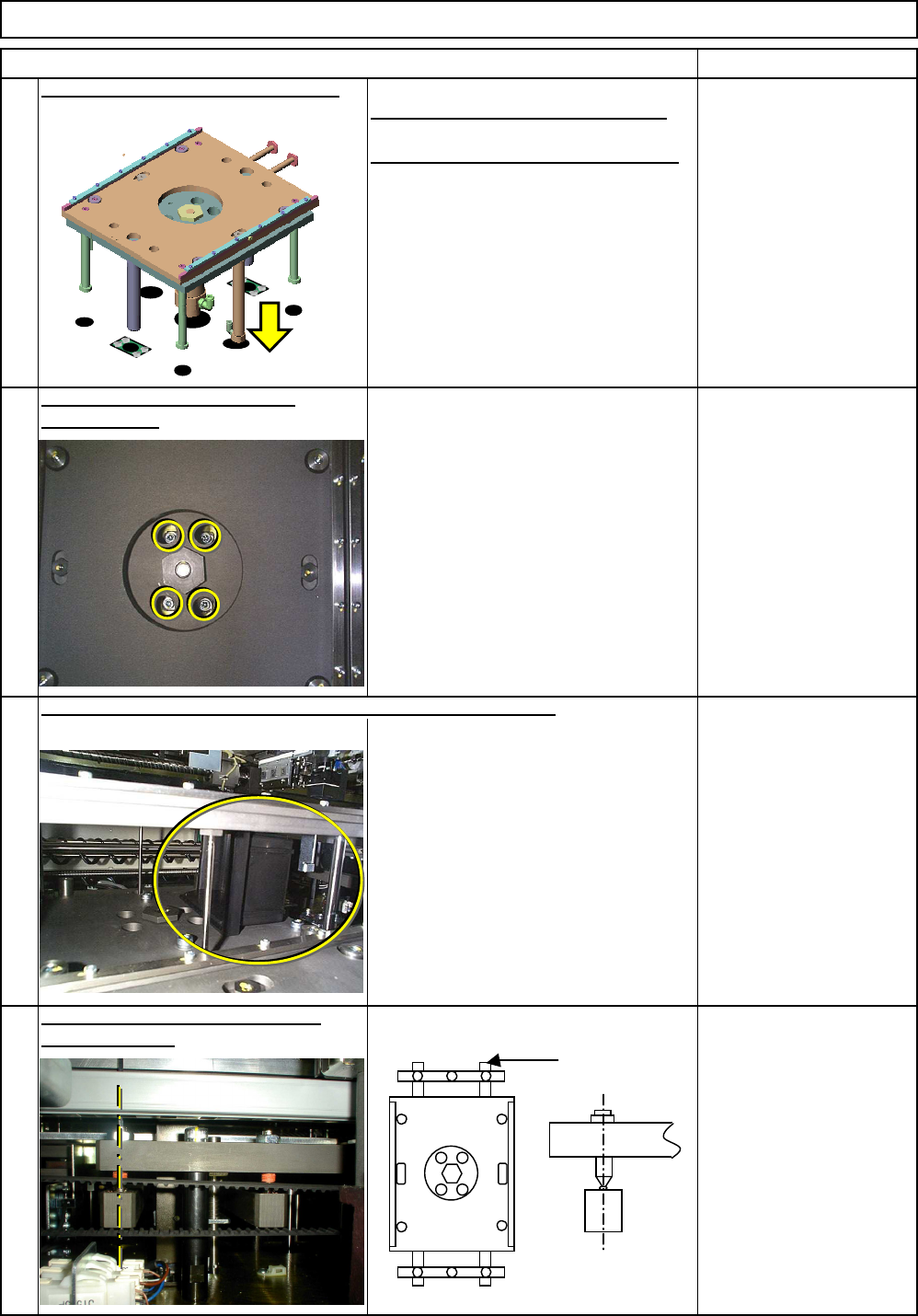
Tighten the support plate cylinder
Allen key 5 mm
Screw M6 4 pcs.
19
Tools and Specifications
Raising the sub plate by hand, insert a 100-mm block or equivalent.
Tools and Specifications
holding screws.
Tools and Specifications
determining bars.
20
Position the support-plate upper-limit
Position so that the bar will
be in the center of the stopper.
Bar
EJM8A-E-SMA050201-A01-00
Page 5-2-1-6
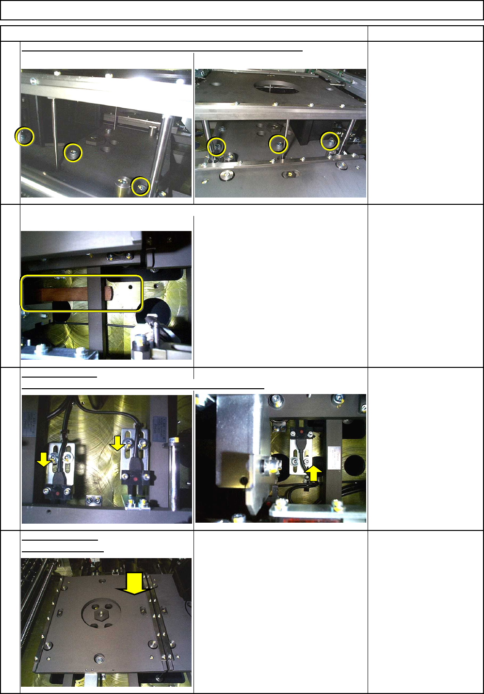
Tighten screws holding the support-plate upper-limit determining bars.
21
Remove the bar from the support-plate upper-limit determining bar
24
Remove the block.
Tools and Specifications
Allen key 5mm
Screw M3 6 pcs.
Tools and Specifications
Allen key 2.5 mm
Screw M3 6 pcs.
The dog and the sensor should not interfere with each other.
22
Sensor Positioning
Tools and Specifications
23
Tools and Specifications
Lower the sub plate.
Board Holder Unit
Item Remark
Machinery Part Replacement
EJM8A-E-SMA050201-A01-00
Page 5-2-1-7
See "Leveling the Support Plate."
Item Remark
Machinery Part Replacement Board Holder Unit
25
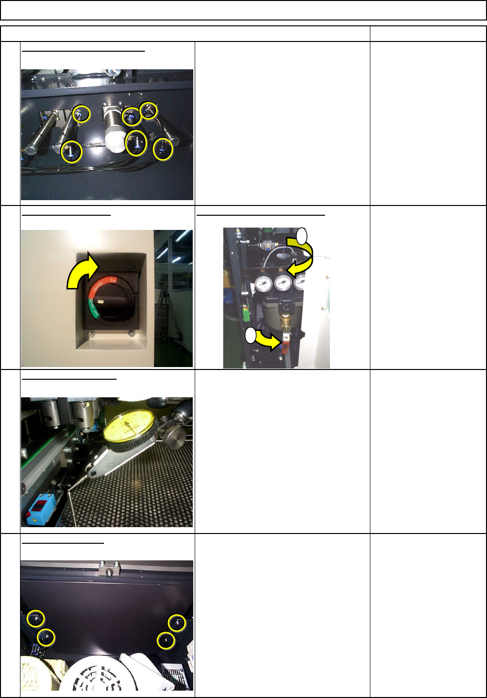
Connect the cylinder air tubes.
Tools and Specifications
26
Supply power and air.
Check that the table is lowered.
Tools and Specifications
27
Level the support plate.
Tools and Specifications
Section 4-1-6
28
Put back the ceiling.
Tools and Specifications
Allen key 3 mm
Screw M4 4 pcs.
1
2
EJM8A-E-SMA050201-A01-00
Page 5-2-1-8