CM602all_EJM8AESM_Service Manual.pdf - 第413页
Machinery Part Replacement REMARKS Light Transfer-Head Assembly (8-nozzle type) ITEM 8 Assemble the holder. Once the housing has been fitted, move the housing along the spline shaft approximately 5 mm a couple of times s…
Machinery Part Replacement
REMARKS
Light Transfer-Head Assembly (8-nozzle type)
ITEM
Be careful! The spring will jump out. Allen key 2.5 mm
M3 x 6L x 1
There is a bushing inside the holder-
screw hole. Be careful not to lose it.
Allen key 2 mm
M3 x 4L x 1
7
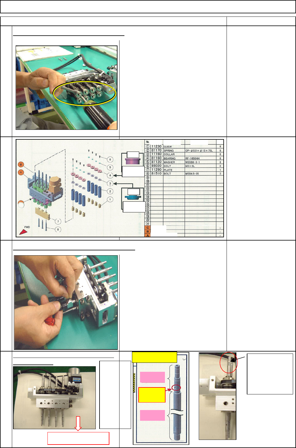
Remove the spline shaft, and replace it
with a new one.
Remove the bearings from the spline shaft.
Remove the holder and the joint from the shaft.
4
5
6
Pull out the shaft,
movin
g
it downwards.
Aligning the
spline shaft with
the dowel pin, fit
it in the original
position.
Apply
grease to
the spline
shaft.
* Be careful
that there
are two
types of
grease to
use.
Be careful of
orientation.
Upper
Upper
Be careful of
orientation.
Spline shaft:
Grease areas and types
B:
BARRIERTA
A:
MP Grease
* Vacuum hole:
Do not apply
to this part.
Part Part Name Model Q
t
Bracket
Ball s
p
lin
e
Theta-axis housin
g
EJM8A-E-SMA050302-A01-00
Page 5-3-2-3
Machinery Part Replacement
REMARKS
Light Transfer-Head Assembly (8-nozzle type)
ITEM
8
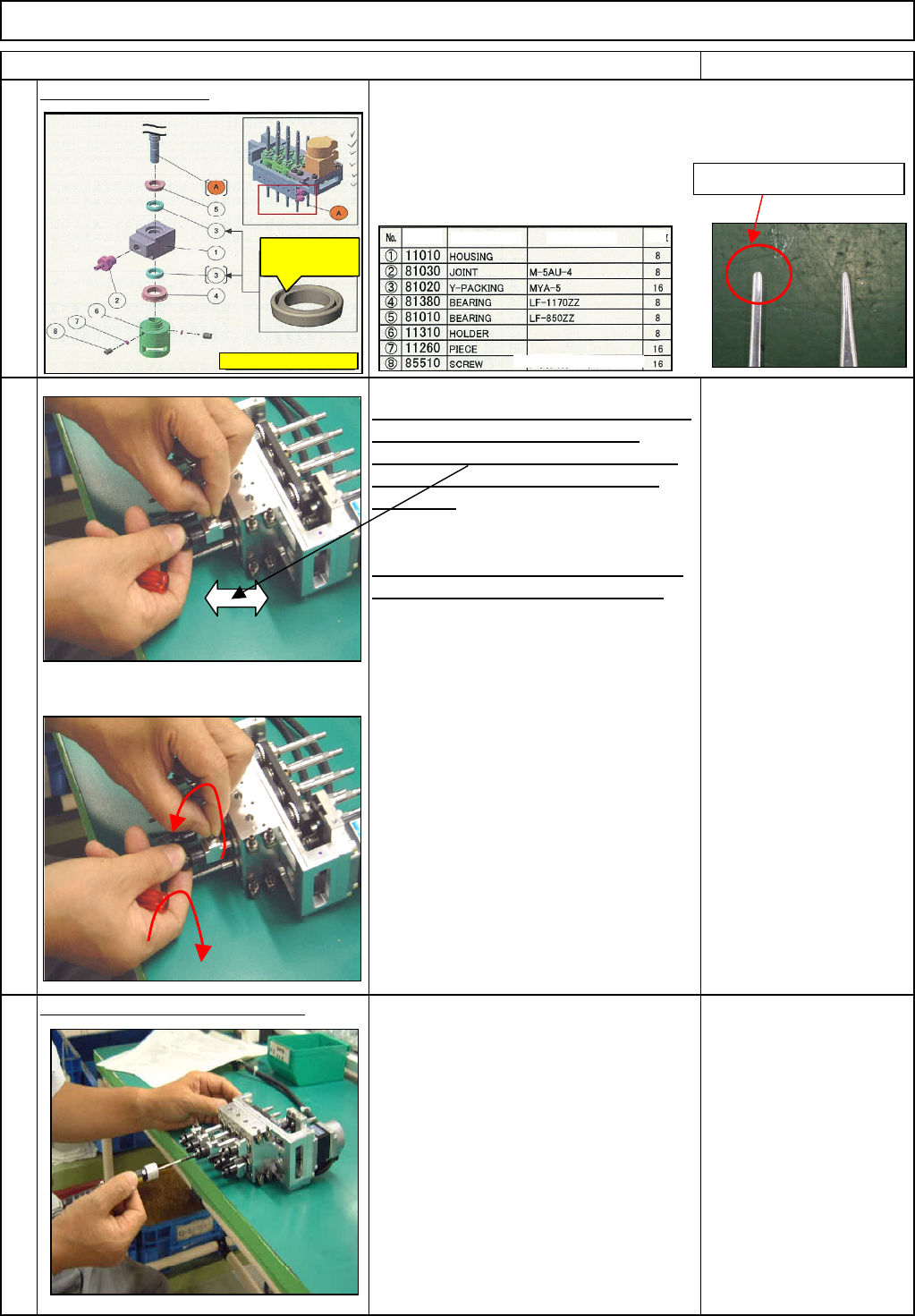
Assemble the holder.
Once the housing has been fitted, move
the housing along the spline shaft
approximately 5 mm a couple of times
so that the Y-shaped packing will be
smoothed.
* Be sure to push the housing fully until
there is no gap. Tighten the housing.
Check that the housing rotates smoothly,
moving the housing left to right a couple
of times
Check the spline shaft for sliding.
1. Sliding torque specifications:
1.47 N or less
• Tension gauge
To avoid damaging the Y-shaped packing, use tweezers whose end
is round and make its edges round before fitting the Y-shaped
packing into the housing.
9
10
Make the edge round
Part
Part Name
Model
Qt
8 sets should be created and fit.
The groove side should
be outside of (1)
Hexahon
-
hole screw
EJM8A-E-SMA050302-A01-00
Page 5-3-2-4
Machinery Part Replacement
REMARKS
Light Transfer-Head Assembly (8-nozzle type)
ITEM
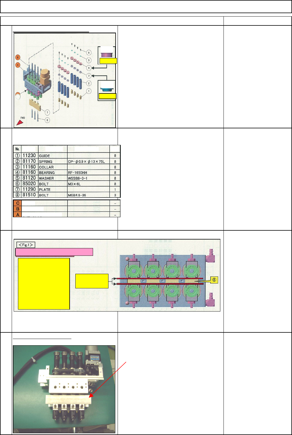
Fit the spring and the bearing.
• MP Grease 2S
• Locktite 242
3. Fit (7) onto (A) with (8).
• Referring to Fig. 1, check that
there is gap between each axis
and (7). Fix (7)
Allen key 2.5 mm
Screw M3 x 6L
Install the theta unit (1)
Put the plate so that the theta unit is
installed and removed more easily.
Plate
12
1. Slightly apply grease to both ends of (2) and the
section of (3) that makes contact with (2).
• Spread designated grease onto vinyl sheet or an
equivalent tool. Lightly put both ends of (2) on that
sheet. (Do not apply grease excessively.)
Slightly apply grease to the section of (3) that makes
contact with (2). See at left.
2. Insert (1) to (4) onto the ball spline shaft (B).
Tighten it with (6) and (5) to which Locktite was
applied.
• Tighten with (6) to which Locktite was applied.
* When assembling, be careful not to bend or deform
the shaft (B).
11
13
Figure when seen from bottom (8)
Put a feeler gauge
between (8) and shafts
as shown at right, and
check the feeler gauge
passes through
smoothly.
Feeler gauge
(0.1 mm)
Bracke
B
a
ll
sp
lin
e
Theta
-
axis housing
Part Part
Model
Qt
y
Upper
Orientation.
Orientation.
Upper
EJM8A-E-SMA050302-A01-00
Page 5-3-2-5