CM602all_EJM8AESM_Service Manual.pdf - 第428页
Machinery Part Replacement Remarks Switch off the main power and air supply. Remove the head assembly. Refer to "Transfer Head Replacement." Section 5-3-1 Separate the Z unit from the board. Refer to "Sepa…
Machinery Part Replacement
This section describes the procedures for replacing the Z-axis motor.
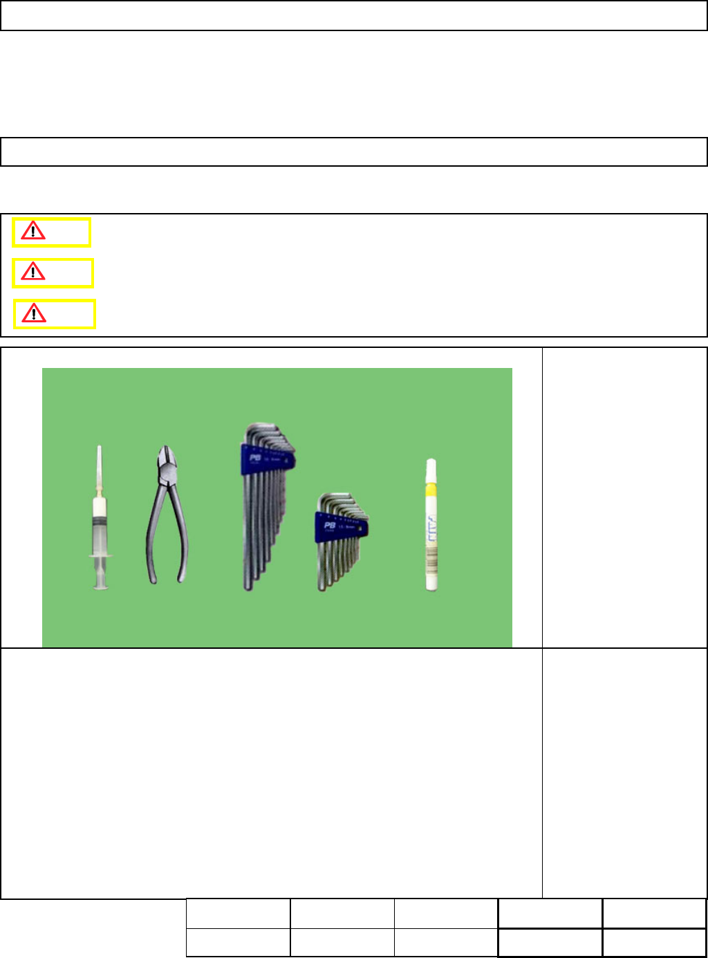
・Tools
Allen key 2 mm
Allen key 2.5 mm
Nipper
Magic marker
MP Grease 2S
・Jig
None
L
ight Transfer-Head Assembly (8-nozzle type
)
5-3-6 Z-axis Motor Replacement
Caution
Dange
r
Warning
Assembly
A
d
j
ustment
55min.
Teaching
min.
Total Time Weight of
Part
Removal
Disassembl
y
55min.
110min.
kgs
EJM8A-E-SMA050306-A01-00
Page 5-3-6-1
Machinery Part Replacement
Remarks
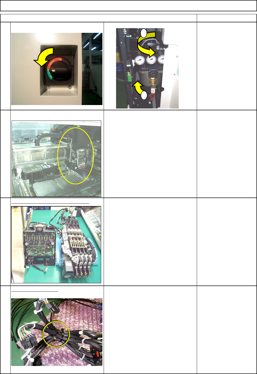
Switch off the main power and air supply.
Remove the head assembly.
Refer to "Transfer Head Replacement." Section 5-3-1
Separate the Z unit from the board.
Refer to "Separating the Z-Unit from the
Board."
Left: Z-axis controlling board
Right: Z-axis drive unit
Section 5-3-14
Cut off the cable ties.
Nipper
L
ight Transfer-Head Assembly (8-nozzle type
)
Item
3
4
1
2
1
2
EJM8A-E-SMA050306-A01-00
Page 5-3-6-2
Machinery Part Replacement
Remarks
L
ight Transfer-Head Assembly (8-nozzle type
)
Item
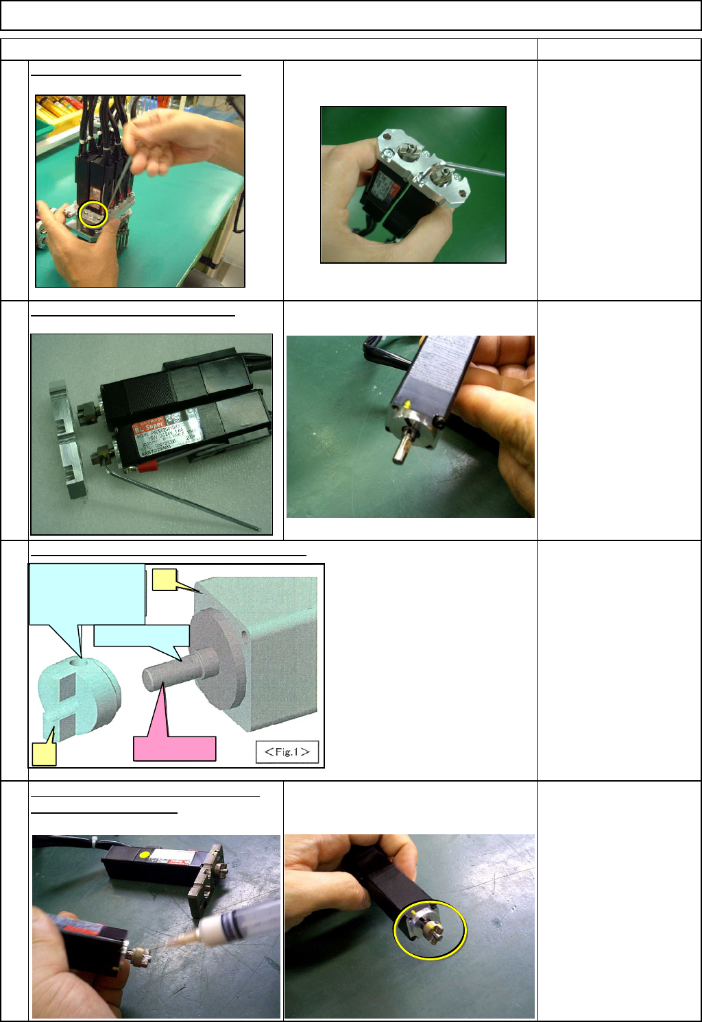
Remove the motor holdin
g
screws.
Allen key 3 mm
Screw M4x16L 2 pcs.
Remove the motor from the plate.
Z-axis motor removed from the machine Allen key 2.5 mm
Screw M3x8L 2 pcs.
Magic marker
A
ppl
y
a small amount of
g
rease to the
Tighten the set-screw, aligning the
joint of the Z-axis motor.
set-screw hole with the D-shaped cut
on the motor shaft.
Allen key 2 mm
MP Grease 2S
Relationship of motor shaft and joint positions
8
5
6
7
D: Align the set-screw
hole of (2) with the D-
shaped cut on (1)
(2)
(1)
C: D-shaped cut
Motor shaft
EJM8A-E-SMA050306-A01-00
Page 5-3-6-3