CM602all_EJM8AESM_Service Manual.pdf - 第433页
Machinery Part Replacement Remarks Switch off the main power and air supply. From 0.49MPa to 0.55MPa Remove the head assembly. Refer to "Transfer Head Replacement." Section 5-3-1 Separate the theta unit from th…
Machinery Part Replacement
This section describes the procedures for replacing the theta-axis motor.
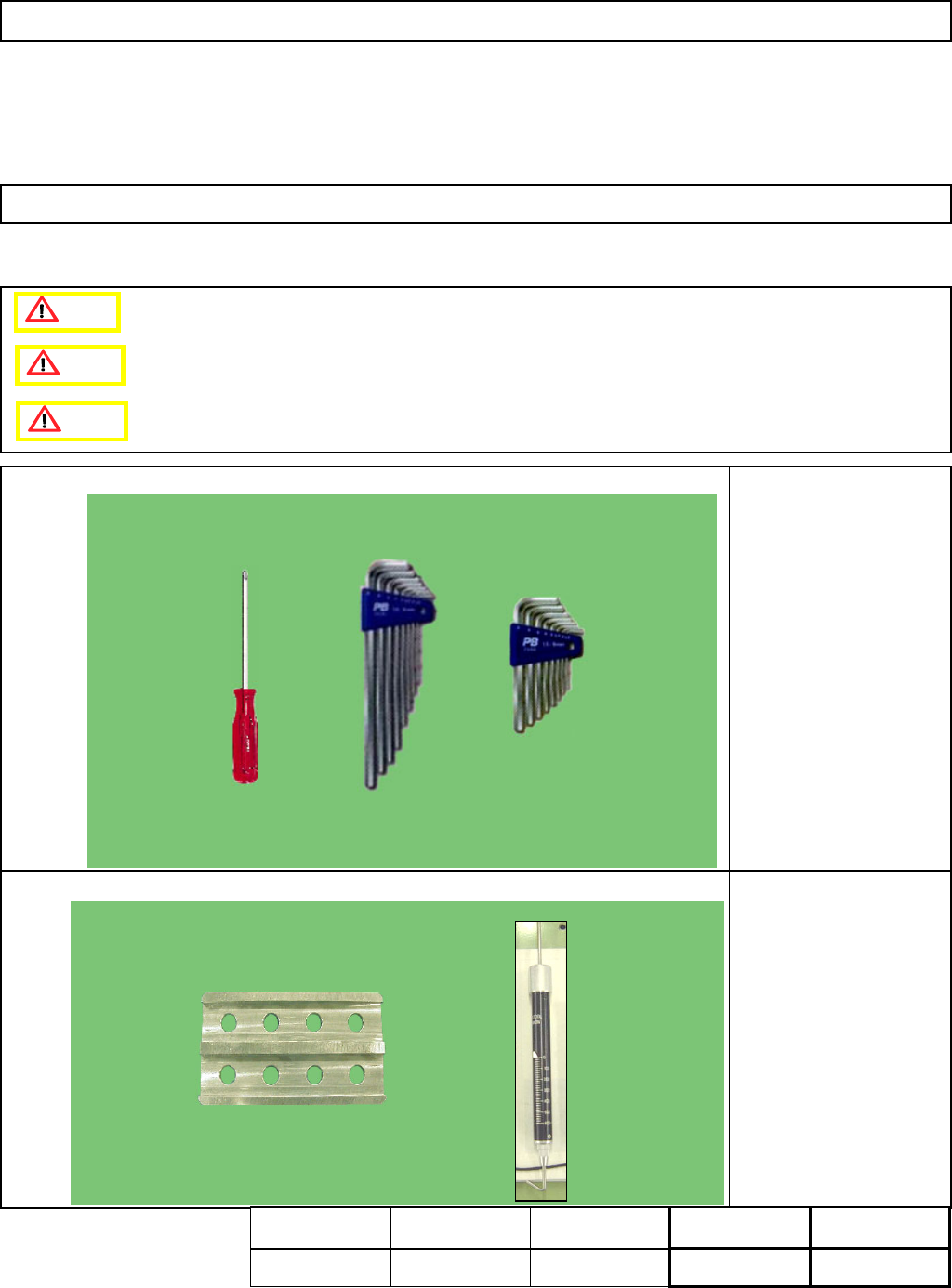
・Tools
Phillips screwdriver #1
Allen key 1.5 mm
Allen key 3 mm
Tension gauge
・Jig
FM-1056
Theta Adjusting Jig
Tension gauge
5-3-7 Theta-axis Motor Replacement
L
ight Transfer-Head Assembly (8-nozzle type
)
Caution
Dange
r
Warning
Assembly
Adjustment
80min.
Teaching
77min.
TotalTime Weightof
Part
Removal
Disassembly
40min.
197min.
kgs
EJM8A-E-SMA050307-A01-00
Page5-3-7-1
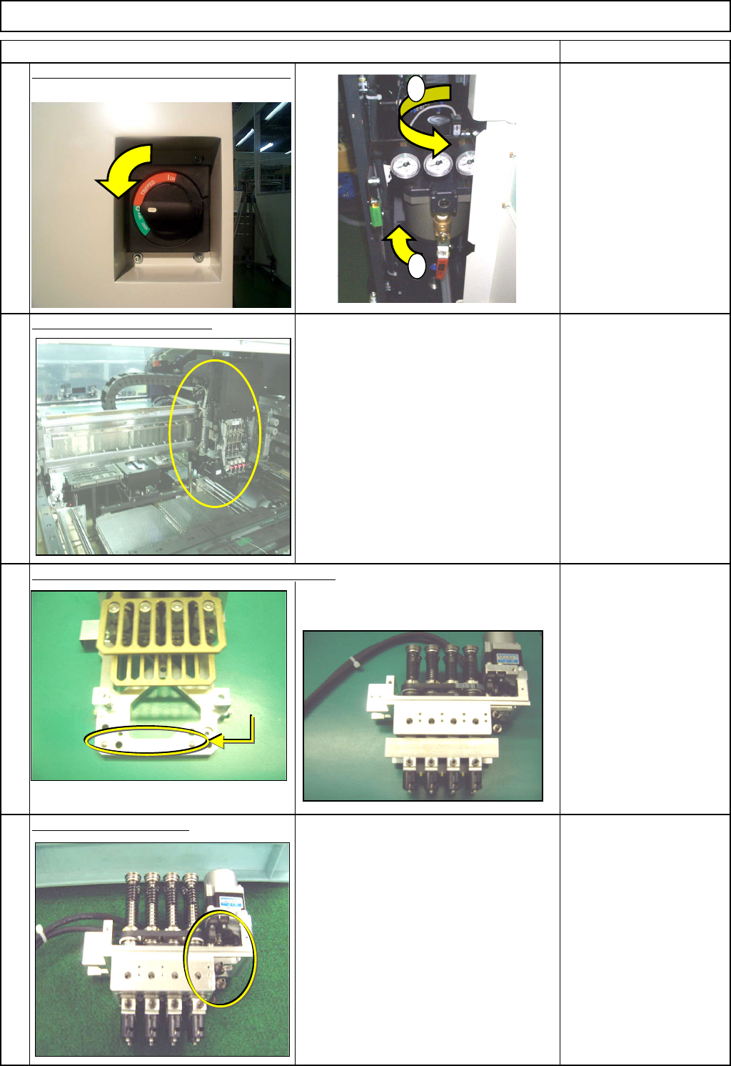
Machinery Part Replacement
Remarks
Switch off the main power and air supply.
From 0.49MPa
to 0.55MPa
Remove the head assembly.
Refer to "Transfer Head Replacement." Section 5-3-1
Separate the theta unit from the head assembly.
Refer to "Theta Unit Removal." Section 5-3-13
Remove the belt tension.
Allen key 3 mm
Screw M4 2 pcs.
4
1
L
ight Transfer-Head Assembly (8-nozzle type
)
Item
2
3
1
2
Dowel pin
EJM8A-E-SMA050307-A01-00
Page5-3-7-2
Machinery Part Replacement
Remarks
L
ight Transfer-Head Assembly (8-nozzle type
)
Item
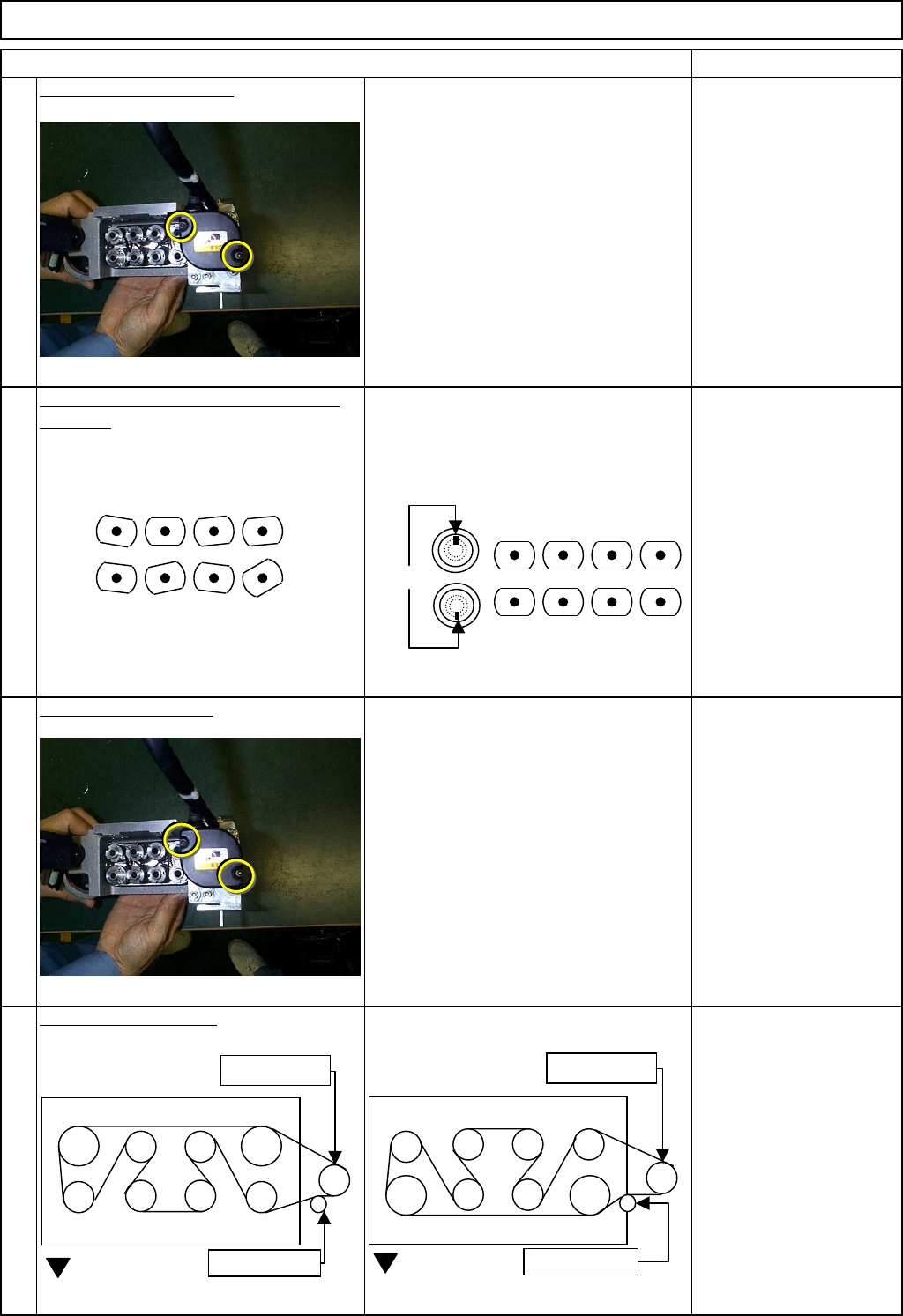
Remove the theta motor.
1-000319
As the theta motor is removed, the belt
gear becomes out of position.
Allen key 3 mm
Screw M4 2 pcs.
Position the nozzle holders in the theta
direction. Position the nozzle holders so that the
set-screws of the nozzle holder will face
outwards. Check by eye.
The set-screws of Nozzle
Holders 1 to 4 should be
positioned opposite those
of Nozzle Holders 5 to 8.
Install the theta motor.
1-000319
Allen key 3 mm
Screw M4 2 pcs.
Adjust the belt tension.
Specification: 1.5 kg/cm
Allen key 3 mm
Screw M4 2 pcs.
5
7
8
6
1
7685
4 23
1
7685
4 23
NG
OK
Set screws
Lower belt
Motor gear
Tension pulley
FWD
Upper belt
Motor gear
Tension pulley
FWD
EJM8A-E-SMA050307-A01-00
Page5-3-7-3