CM602all_EJM8AESM_Service Manual.pdf - 第434页
Machinery Part Replacement Remarks L ight Transfer-Head Assembly (8-nozzle type ) Item Remove the theta motor. 1-000319 As the theta motor is removed, the belt gear becomes out of position. Allen key 3 mm Screw M4 2 pcs.…
Machinery Part Replacement
Remarks
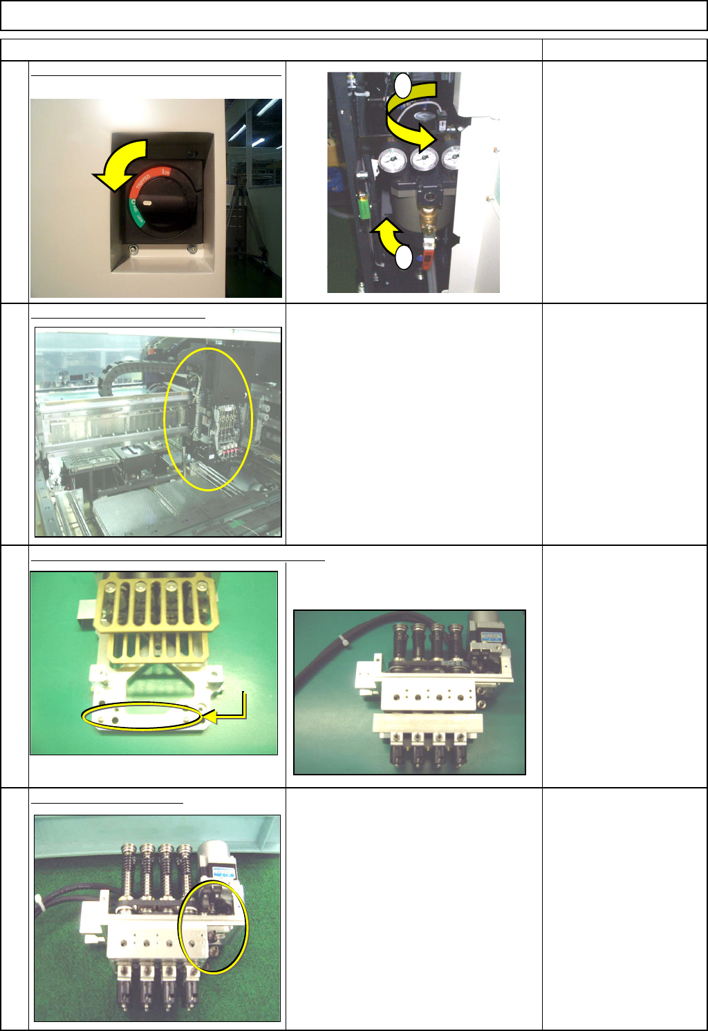
Switch off the main power and air supply.
From 0.49MPa
to 0.55MPa
Remove the head assembly.
Refer to "Transfer Head Replacement." Section 5-3-1
Separate the theta unit from the head assembly.
Refer to "Theta Unit Removal." Section 5-3-13
Remove the belt tension.
Allen key 3 mm
Screw M4 2 pcs.
4
1
L
ight Transfer-Head Assembly (8-nozzle type
)
Item
2
3
1
2
Dowel pin
EJM8A-E-SMA050307-A01-00
Page5-3-7-2
Machinery Part Replacement
Remarks
L
ight Transfer-Head Assembly (8-nozzle type
)
Item
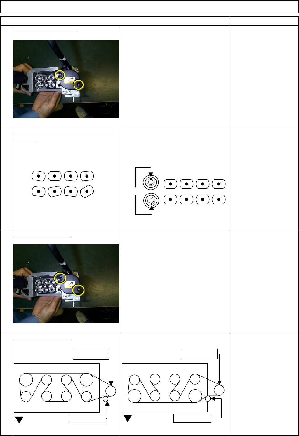
Remove the theta motor.
1-000319
As the theta motor is removed, the belt
gear becomes out of position.
Allen key 3 mm
Screw M4 2 pcs.
Position the nozzle holders in the theta
direction. Position the nozzle holders so that the
set-screws of the nozzle holder will face
outwards. Check by eye.
The set-screws of Nozzle
Holders 1 to 4 should be
positioned opposite those
of Nozzle Holders 5 to 8.
Install the theta motor.
1-000319
Allen key 3 mm
Screw M4 2 pcs.
Adjust the belt tension.
Specification: 1.5 kg/cm
Allen key 3 mm
Screw M4 2 pcs.
5
7
8
6
1
7685
4 23
1
7685
4 23
NG
OK
Set screws
Lower belt
Motor gear
Tension pulley
FWD
Upper belt
Motor gear
Tension pulley
FWD
EJM8A-E-SMA050307-A01-00
Page5-3-7-3
Machinery Part Replacement
Remarks
L
ight Transfer-Head Assembly (8-nozzle type
)
Item
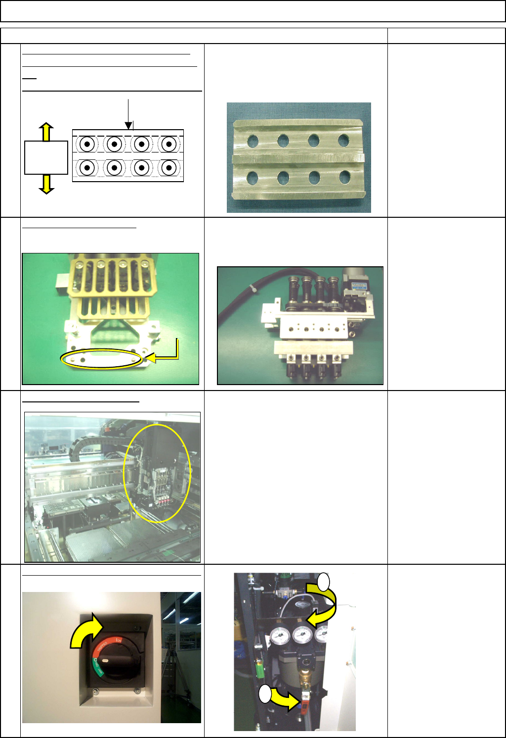
Place the plate jig on the bottom of the
theta unit. Check that the nozzle holders
are
positioned precisely in the theta direction.
Adjust the angle of each nozzle to 0°.
The set-screws of Nozzle Holders 1 to 4
should be positioned opposite those of
Nozzle Holders 5 to 8.
Nozzle theta angle
position:
Specification: +/- 0.5°
Jig: Nozzle theta adjusting
jig
Fix lightly; after installing
the head, adjust.
Allen key 1.5 mm
See Section 4-1-8.
Set-screw 2mm 8 pcs.
Put the theta unit back on.
Refer to "Theta Unit Removal." Section 5-3-13
Refer to "Head Assembly Replacement." Section 5-3-1
Switch on the main power and air supply.
12
9
10
11
Set-screws
should
face
td
Adjusting jig
Seen from bottom of the head
1
2
Dowel pin
EJM8A-E-SMA050307-A01-00
Page5-3-7-4