CM602all_EJM8AESM_Service Manual.pdf - 第497页
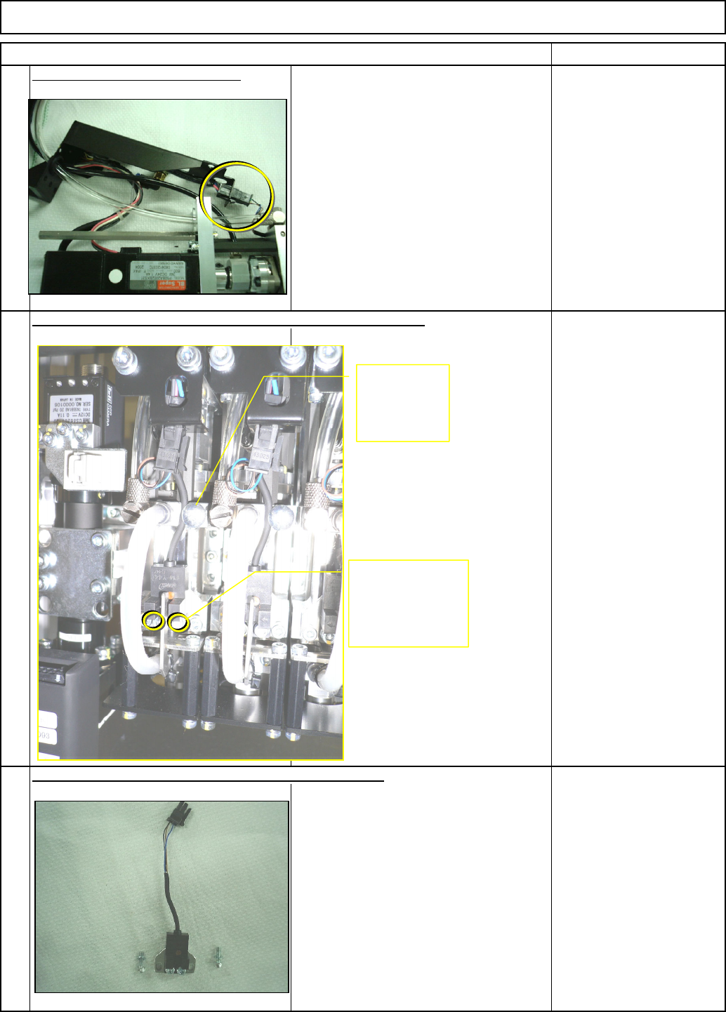
* Sensor installation * Securin g the sensor cable Be careful of cable-cau g ht. Switch ON the power. Tool/Spec/Installation 9 Connect the sensor connector. Machinery Part Replacement Z Unit (3-nozzle type) Item Remarks …
6
Tool/Spec/Installation
Allen key 2.5 mm
Screw M3 2 pcs.
Tool/Spec/Installation
7
Remove the sensor holding screws. Replace the sensor.
Tool/Spec/Installation
Disconnect the sensor connector.
5
Z Unit (3-nozzle type)
Remarks
Machinery Part Replacement
Item
Remove the sensor-cable-holding screws. Remove the sensor.
Allen key 3 mm
Screw M4 2 pcs.
Remove the
cable-holding
screw.
Remove the
sensor-holding-
bracket screw.
EJM8A-E-SMA050501-A01-00
Page 5-5-1-3
* Sensor installation
* Securin
g
the sensor cable
Be careful of cable-cau
g
ht.
Switch ON the power.
Tool/Spec/Installation
9
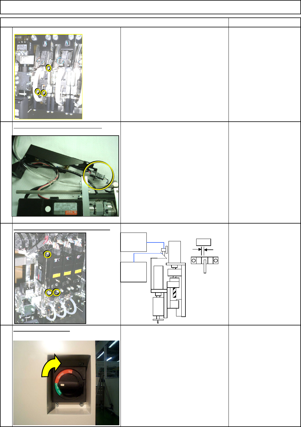
Connect the sensor connector.
Machinery Part Replacement
Z Unit (3-nozzle type)
Item Remarks
Allen key 3 mm
Screw M4 2 pcs.
Allen key 3 mm
Screw M4 3 pcs.
The sensor and the dog
should not interfere with
each other.
11
8
Tighten the cover holding screws.
Tool/Spec/Installation
10
Tool/Spec/Installation
Z-axis
rough origin
PH
Z-axis
rough origin
dog
Gap
EJM8A-E-SMA050501-A01-00
Page 5-5-1-4
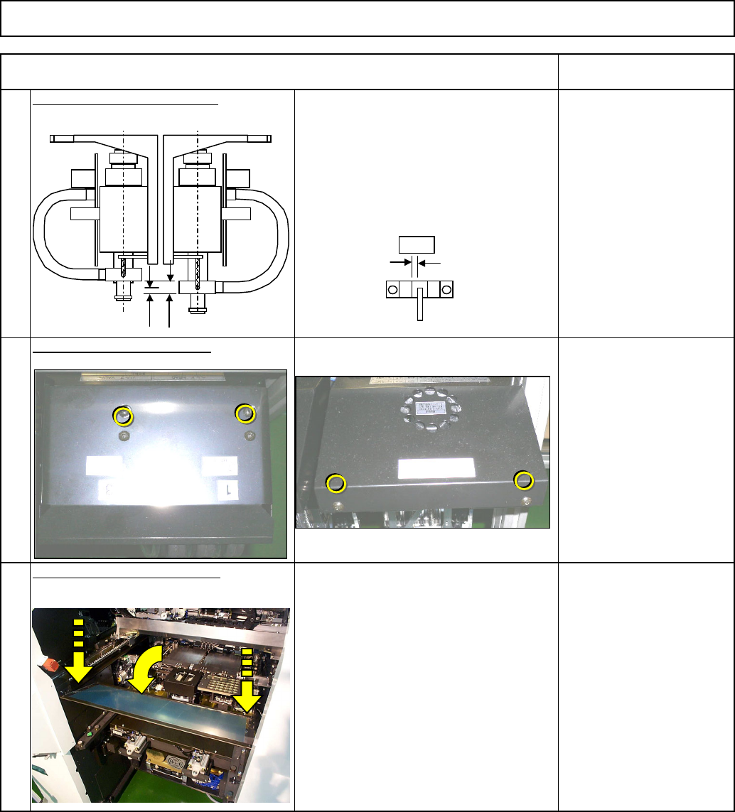
end sensor should turn ON.
* The dog and the sensor should not
interfere with each other.
12
Position the sensor precisely.
Tool/Spec/Installation
* When the end cylinder ascends by the
amount of S1 stroke, the cushion
Caliper 150 mm
Cushion stroke
S0 = 8 mm /0+0.2
Cushion-end-sensor ON
S1 = 2 mm +/- 0.2
Machinery Part Replacement
Z Unit (3-nozzle type)
13
Put the head cover back on.
Tool/Spec/Installation
Phillips screwdriver #1
Phillips screwdriver #2
Screw M3 2 pcs.
Screw M4 2 pcs.
14
Put the feeder cover back on.
Tool/Spec/Installation
Phillips screwdriver #2
Screw M4 2 pcs.
Item Remarks
S0
S1
Gap
EJM8A-E-SMA050501-A01-00
Page 5-5-1-5