CM602all_EJM8AESM_Service Manual.pdf - 第519页
Machinery Part Replacement Remarks Item Z Unit (3-nozzle type) from falling. After the motor is removed, the axis will become free and may fall. Remove the Z-axis motor holding screws. Allen key 3 mm Screw M4 2 pcs. Rais…
Machinery Part Replacement
Remarks
Switch off the main power.
Remove the top cover from the head assembly.
Phillips screwdriver #1
Phillips screwdriver #2
Screw M3 2 pcs.
M4 2 pcs.
Disconnect the connector from the head.
Remove the front motor bracket.
Allen key 3 mm
Screw M4 3 pcs.
1
Item
2
Z Unit (3-nozzle type)
3
4
EJM8A-E-SMA050505-A01-00
Page 5-5-5-2
Machinery Part Replacement
Remarks
Item
Z Unit (3-nozzle type)
from falling.
After the motor is removed, the axis will
become free and may fall.
Remove the Z-axis motor holding screws.
Allen key 3 mm
Screw M4 2 pcs.
Raise the motor and remove it.
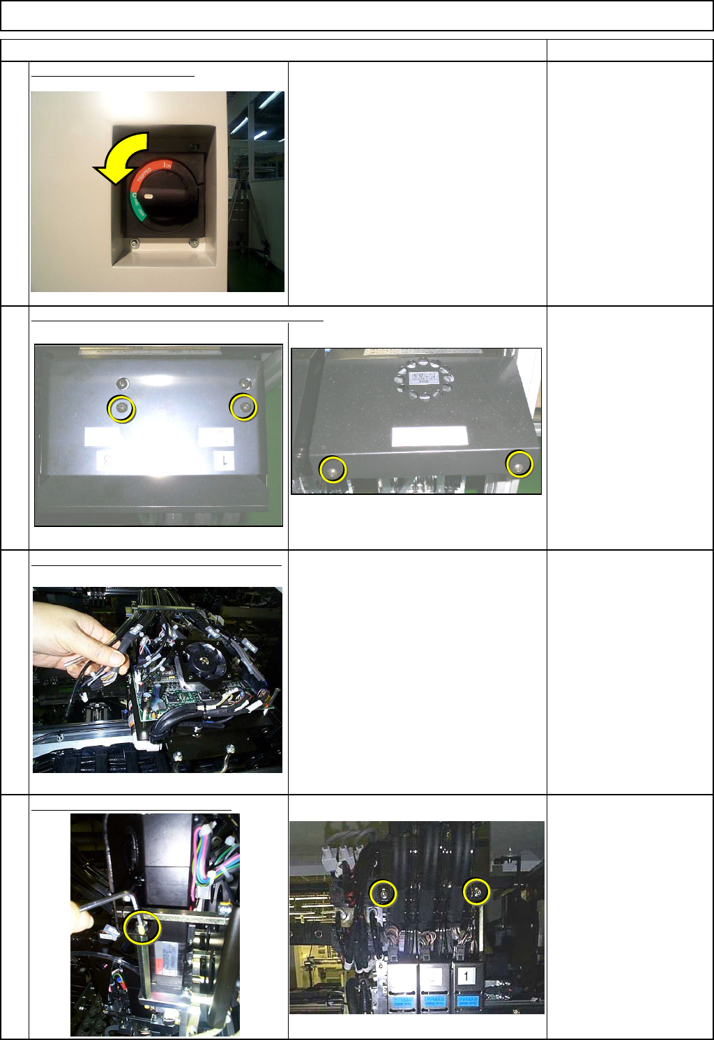
Remove the set screws. Replace the joint.
Allen key 2 mm
Set screw M3 1 pc.
Insert a 2-mm Allen key from the rear side of the head in order to prevent the Z-axis
5
6
7
8
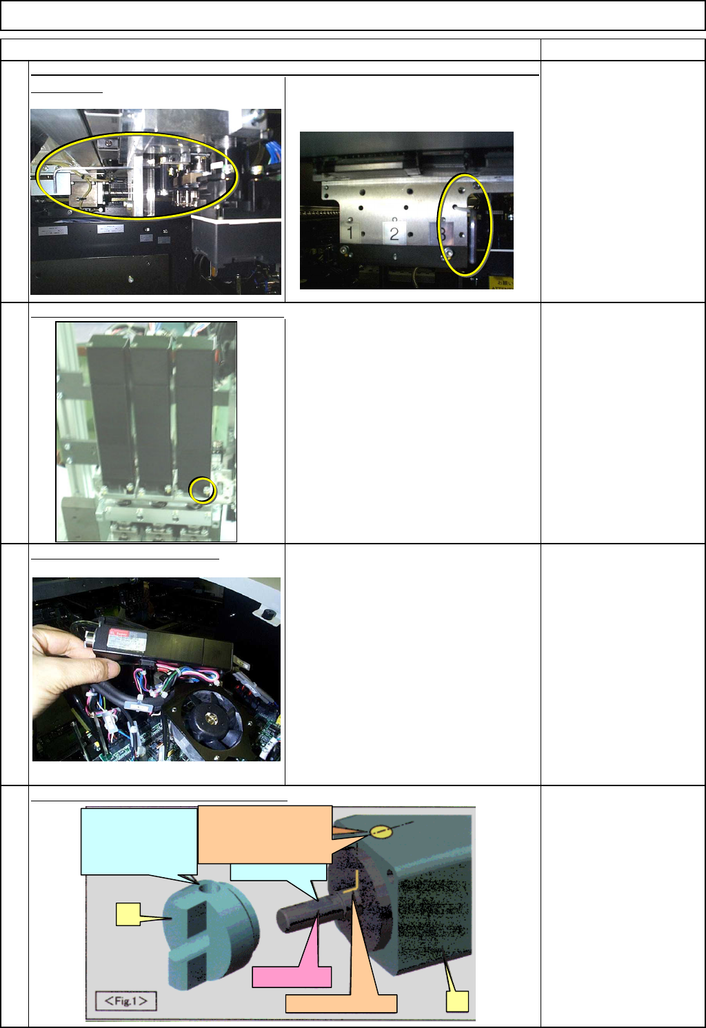
D: Align the set-screw
hole of (2) with the D-
shaped cut on the
motor shaft
(2)
(1)
B: Put a yellow mark so
that
the position of Mark A will
be easily recognized.
A
: Mark put by Make
r
C: D-shaped cut
Motor shaft
EJM8A-E-SMA050505-A01-00
Page 5-5-5-3
Machinery Part Replacement
Remarks
Item
Z Unit (3-nozzle type)
Apply a small amount of grease to the joint.
BARRIERTA
Looking from above, align the motor joint and the shaft joint at a point more than
90 degrees from the mark.
Tighten the Z-axis motor set screws.
Allen key 3 mm
Screw M4 2 pcs.
Remove the 2-mm Allen key from the rear side of the head.
9
10
11
12
Set-
screw
Mark
Joint
○
×
Top view
EJM8A-E-SMA050505-A01-00
Page 5-5-5-4