CM602all_EJM8AESM_Service Manual.pdf - 第535页
min . min. min. This section describes the procedures for replacing the Z-axis upper sensor. 5-5-8 Z-axis Upper Sensor Replacement Machinery Part Replacement Z Unit (3-nozzle type) Phillips screwdriver #1 Phillips screwd…
Refer to "Replacing a Set of Head Units."
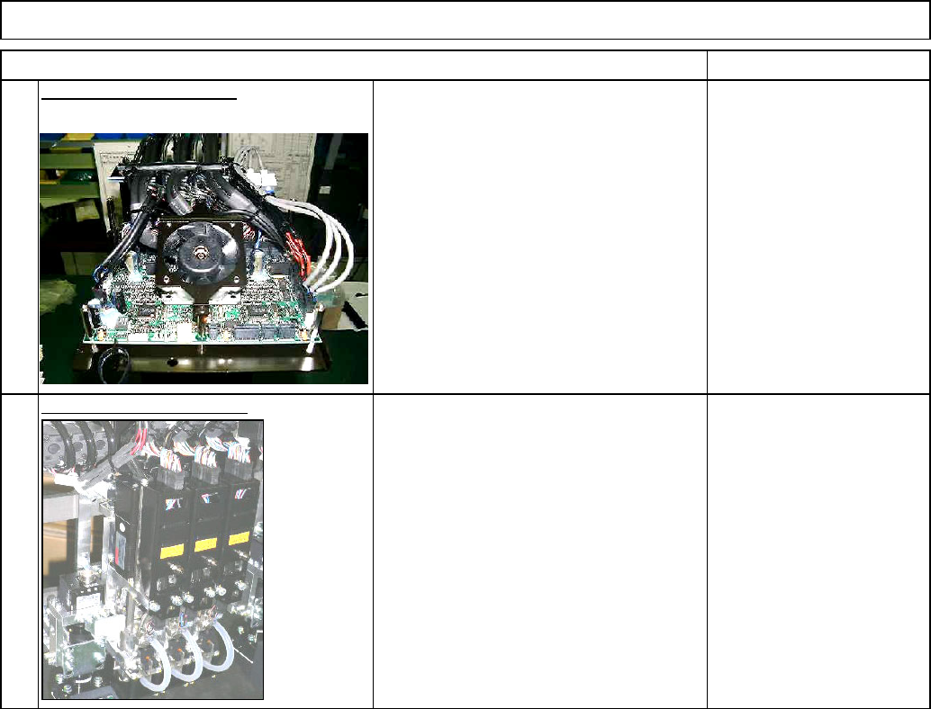
Machinery Part Replacement
Z Unit (3-nozzle type)
Section 5-5-1
Item Remarks
17
Connect the connectors.
Tools and Specifications
Install a set of head units.
Tools and Specifications
18
EJM8A-E-SMA050507-A01-00
Page 5-5-7-6
min
.
min. min.
This section describes the procedures for replacing the Z-axis upper sensor.
5-5-8 Z-axis Upper Sensor Replacement
Machinery Part Replacement
Z Unit (3-nozzle type)
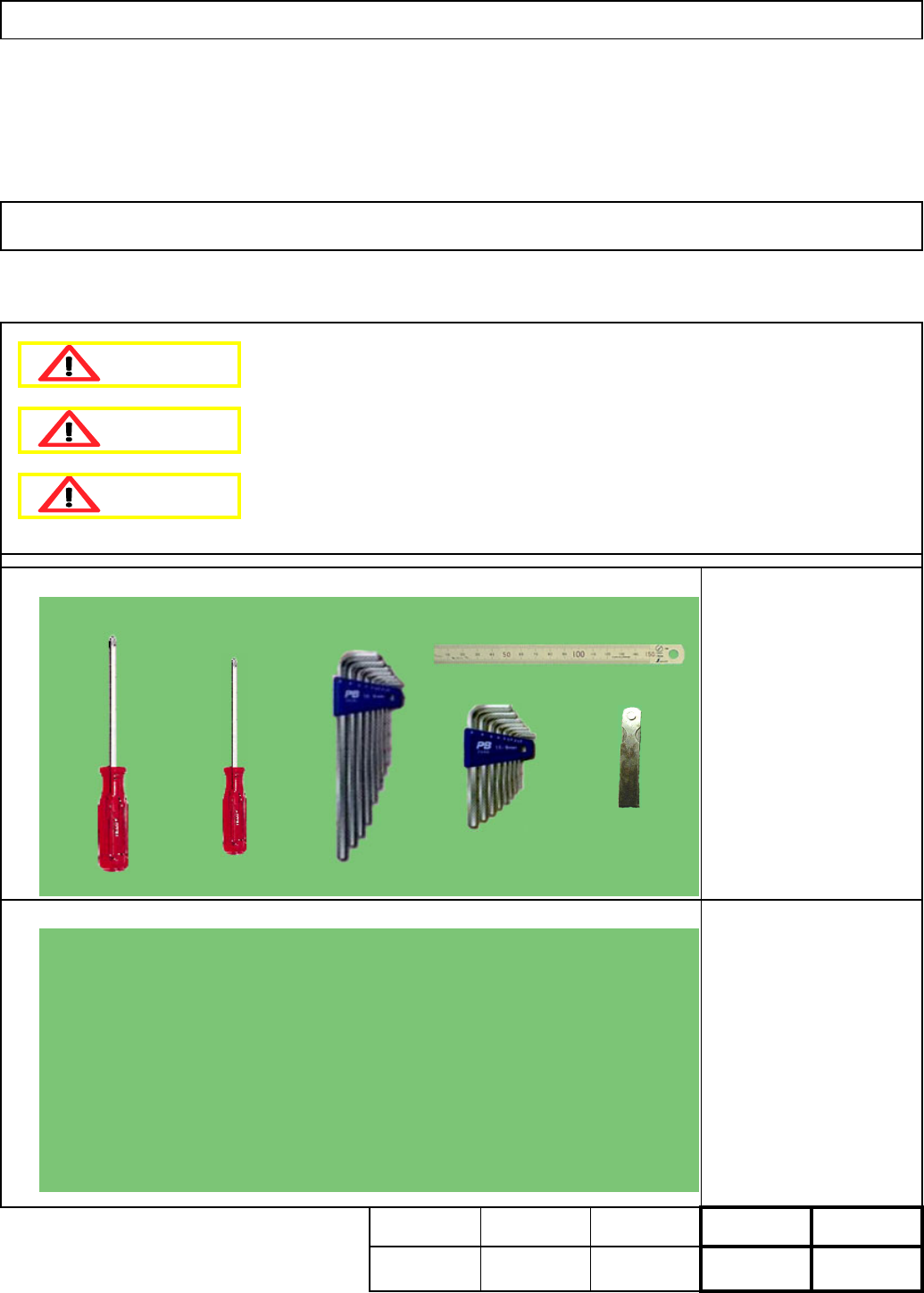
Phillips screwdriver #1
Phillips screwdriver #2
Allen key 2.5 mm
Ruler 150 mm
Feeler gauge
None
• Tools
• Jigs
W
e
i
g
h
t o
f
Par
t
20 min.
45
Removal
Disassembl
y
A
ssembl
y
A
d
j
ustment
Teaching Total Time
Kgs
.
25
Dange
r
Warning
Caution
EJM8A-E-SMA050508-A01-00
Page 5-5-8-1
Z Unit (3-nozzle type)
Tools and Specifications
3
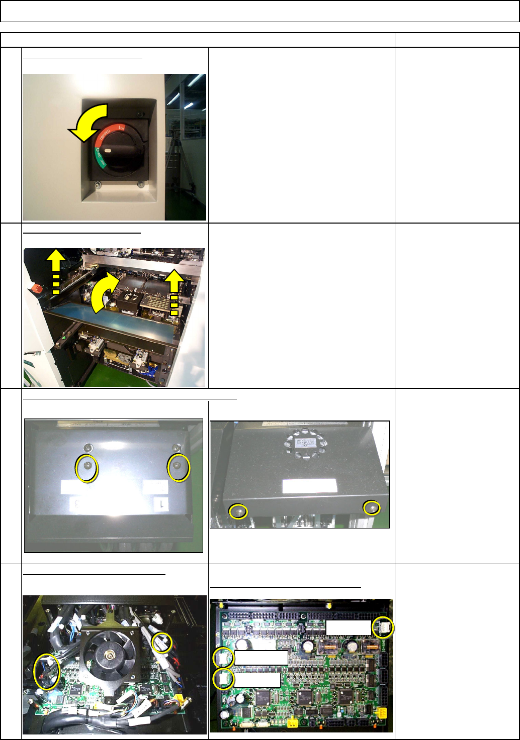
White connectors: Z origin sensor
4
Tools and Specifications
Item Remarks
Tools and Specifications
Phillips screwdriver #1
Phillips screwdriver #2
Screw M3 2 pcs.
M4 2 pcs.
Phillips screwdriver #2
Screw M4 2 pcs.
Tools and Specifications
Remove the top cover from the head assembly.
Remove the sensor connectors.
2
1
Remove the feeder cover.
Switch off the main power.
Machinery Part Replacement
CN10: Z1
CN9: Z2
CN7: Z3
EJM8A-E-SMA050508-A01-00
Page 5-5-8-2