CM602all_EJM8AESM_Service Manual.pdf - 第575页
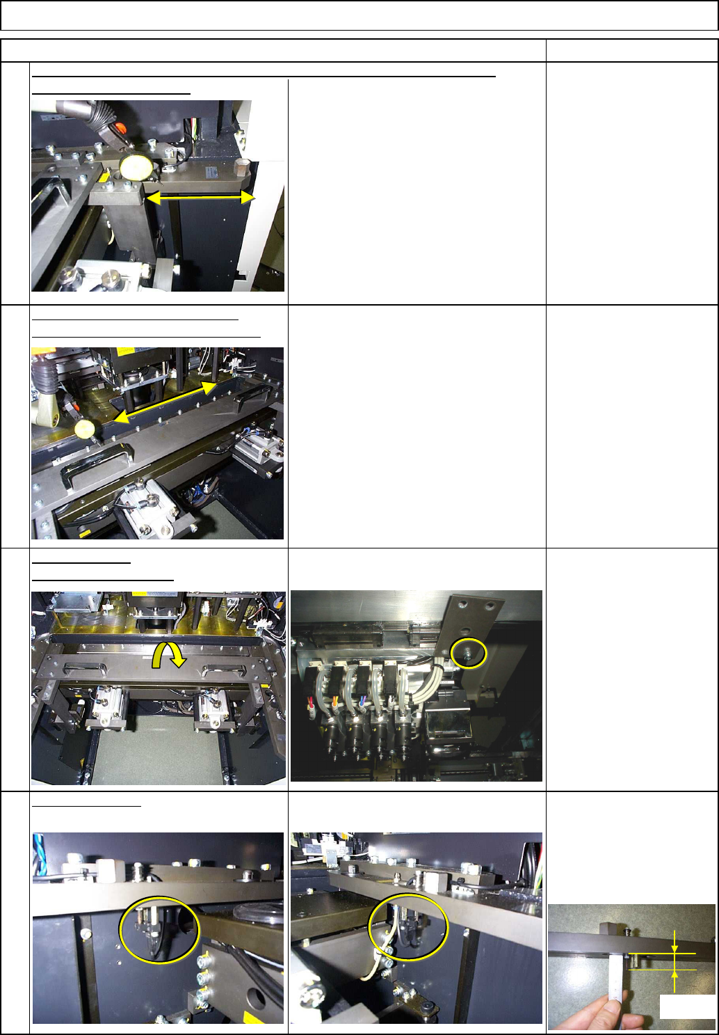
Once the parallelism is achieved, tighten all bolts and loosen the bolts circled at left. To adjust it, move the right bracket, which is half fixed. 14 16 Adjust the jig so that the jig is parallel with the X-axis. 15 Mo…
10
11
12
Allen key 3 mm
Iron plate
Magnetic stand
Dial gauge
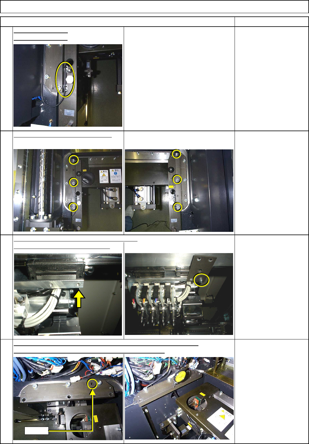
Remove the cart positioning bracket.
Allen key 6 mm
Screw M8 x 30L 6 pcs.
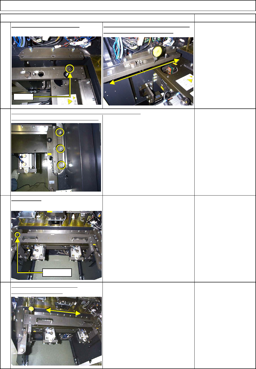
Place a dial gauge on the iron plate.
Place the iron plate on the bottom of the head.
9
Cut off the cable tie.
Item Remarks
Machinery Part Replacement Feeder Cart Installing Section
Referring to the split pin, adjust the section below so that it is parallel
with the Y-axis. (There is a split pin on the left side only.)
Remove the sensor.
Nipper
S
p
lit
EJM8A-E-SMA050802-A01-00
Page 5-8-2-4
Once the parallelism is achieved,
tighten all bolts and loosen the bolts
circled at left.
To adjust it, move the right bracket,
which is half fixed.
14
16
Adjust the jig so that the jig is
parallel with the X-axis.
15
Mount the jig.
(There is no split pins on the right side.)
Adjust the right bracket so that it is parallel with the Y-axis.
Item Remarks
13
Fit the cart positioning bracket.
Referring to the split pin, adjust the bracket
so that it is parallel with the Y-axis.
Machinery Part Replacement Feeder Cart Installing Section
S
p
lit
Reference
EJM8A-E-SMA050802-A01-00
Page 5-8-2-5
20
Allen key 2.5 mm
Screw M3 4 pcs.
19
Remove the jig.
Remove the iron plate.
Allen key 3 mm
Iron plate
Magnetic stand
Dial gauge
Install the sensor.
Once the jig has been adjusted to parallel, adjust the right bracket so that it
18
Confirm the parallelism of the jig.
Tighten the bracket bolts completely.
Machinery Part Replacement Feeder Cart Installing Section
Item Remarks
17
is parallel with the Y-axis.
16.5㎜
EJM8A-E-SMA050802-A01-00
Page 5-8-2-6