CM602all_EJM8AESM_Service Manual.pdf - 第586页
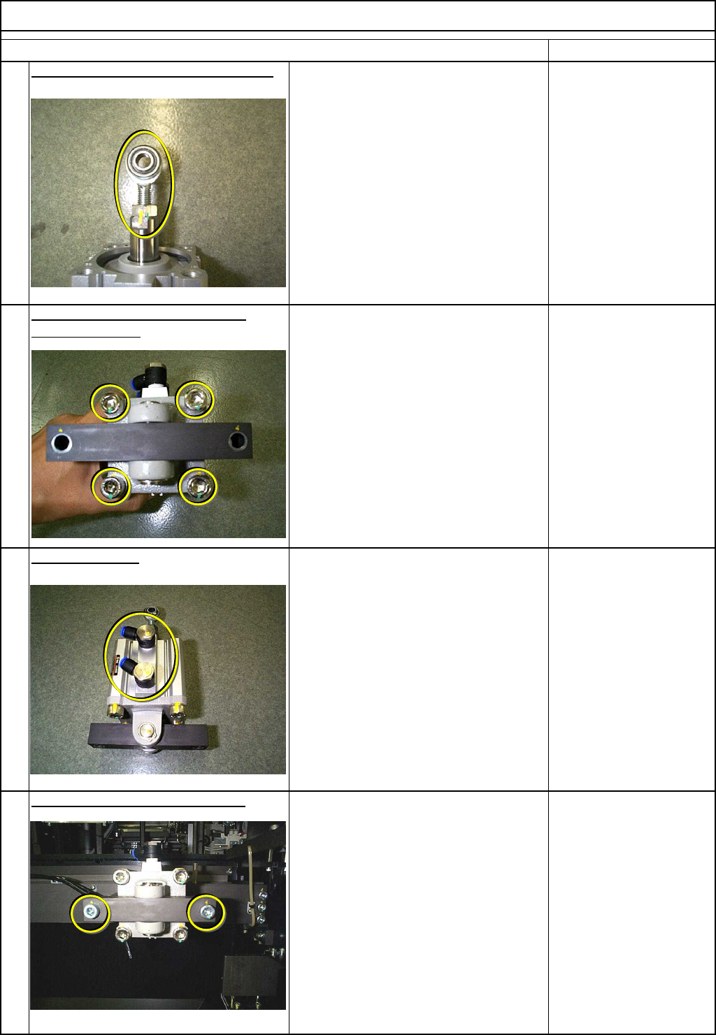
Machinery Part Replacement Remarks Cutting Unit Item Full y ti g hten the rod ends. Allen key 6 mm Screw M8 2 pcs. Remove the chute guide bar. Allen key 4 mm Screw M5 2 pcs. Position the cylinder so that the cutter blade…
Machinery Part Replacement
Remarks
Cutting Unit
Item
Replace the rod end.
(
Li
g
htl
y
ti
g
hten it.
)
Wrench 17 mm
17-mm nut
Replace the c
y
linder holdin
g
block.
(Lightly tighten it.) Allen key 8 mm
Screw M10 4 pcs.
Replace the
j
oint.
Wrench 17 mm
Sealing tape
Install the c
y
linder on the machine.
Allen key 6 mm
Screw M8 2 pcs.
9
12
10
11
EJM8A-E-SMA050902-A01-00
Page 5-9-2-4
Machinery Part Replacement
Remarks
Cutting Unit
Item
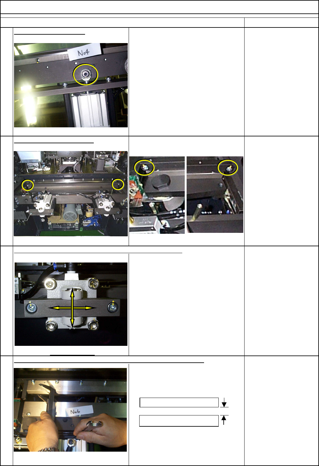
Full
y
ti
g
hten the rod ends.
Allen key 6 mm
Screw M8 2 pcs.
Remove the chute guide bar.
Allen key 4 mm
Screw M5 2 pcs.
Position the cylinder so that the cutter blades move smoothly.
Allen key 8 mm
Screw M10 4 pcs.
Adjust the stroke of the cylinder when the movable cutter is retracted.
Clearance from the fixed cutter blade to
the movable one when the movable one
is at the origin: 26 mm +/- 0.2 mm
Caliper
Wrench 17 mm
13
16
15
14
Fixed blade
Movable blade
26.0mm+/-0.2mm
EJM8A-E-SMA050902-A01-00
Page 5-9-2-5
Machinery Part Replacement
Remarks
Cutting Unit
Item
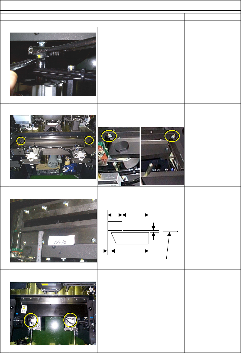
lock the rod-ends. Wrench 17 mm
Put he chute guide bar back on.
Allen key 4 mm
Feeler gauge
Screw M5 2 pcs.
Check the chute guide bar and the return
limit of the movable cutter blade. Put back the chute guide bar, using a
0.1-mm feeler gauge.
Feeler gauge
Caliper
Ruler 150 mm
Connect the cylinder air tubes.
20
With the cutter blades at the extension limit,
17
18
19
Clearance from the guide bar to the movable
cutter blade: 0.05 to 0.2 mm
(0.05-mm feeler gauge should pass through;
0.2-mm one should NOT be inserted.)
45
36.811.2
3±0.5
0.05 - 0.1 mm
0.1-mm feeler gauge
EJM8A-E-SMA050902-A01-00
Page 5-9-2-6