CM602all_EJM8AESM_Service Manual.pdf - 第607页
Machinery Part Replacement Remark Item 12-Nozzle Head Unit Remove the LED connector. Remove the head-holding bolts. Allen key 5 mm Pipe M6 screw 4 pcs. After the screws have been removed, hold the head by hand. (Otherwis…
Machinery Part Replacement
Remark
Item
12-Nozzle Head Unit
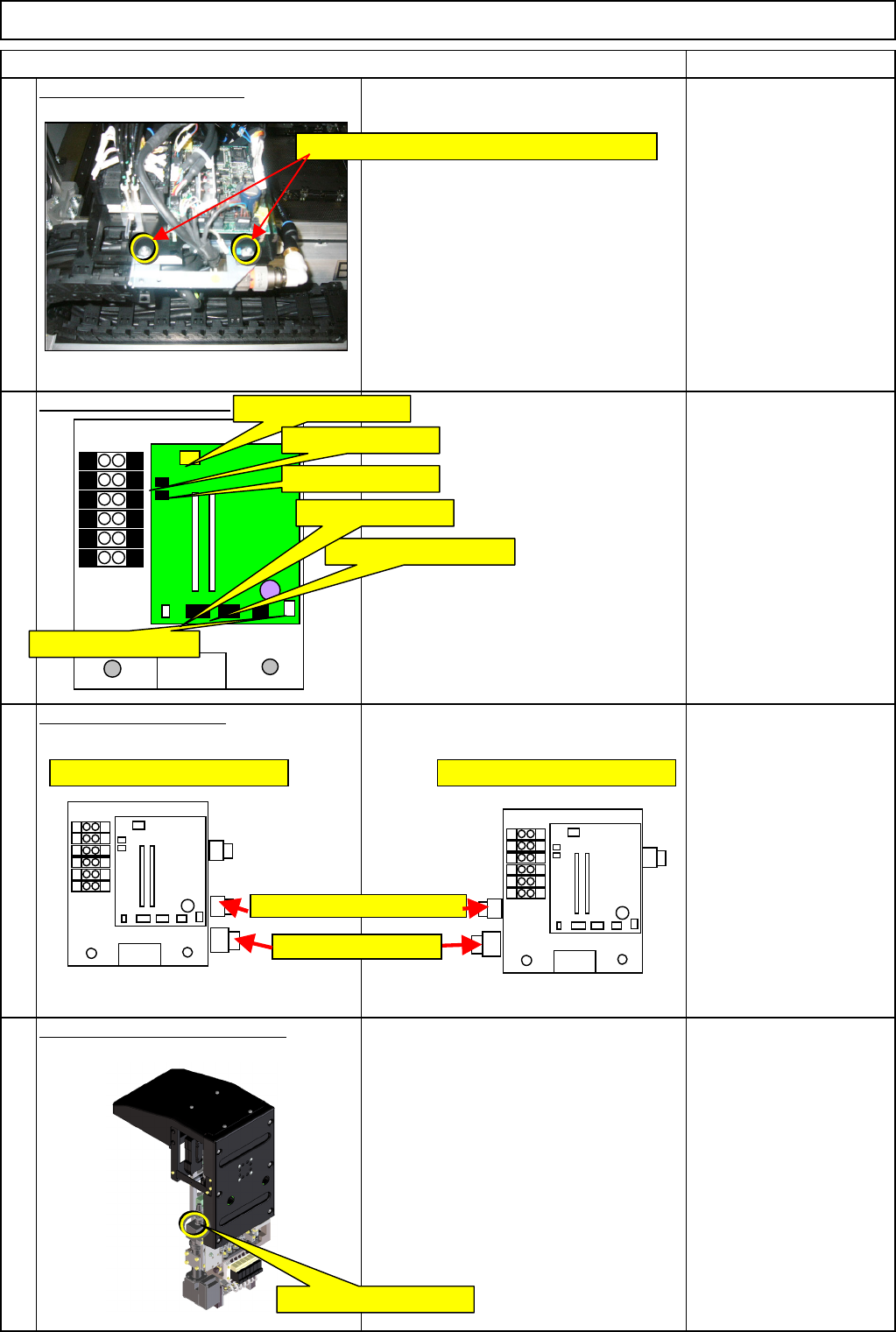
Remove the holding bolts.
Screw M4 x 8L 2 pcs.
Thick washer
Remove the connectors.
Remove the tube joints.
Remove the camera connector.
12
10
11
9
C12-M(st,No)⇒CN12
C8-M(st,No)⇒CN8
C9-M(st,No)⇒CN9
CN2-M(st,No)⇒CN2
CN11-M(st,No)⇒CN11
C1-M(st,No)⇒CN1
Remove the M4×8L screws and the washers.
Positions of AF and BR joints Positions of AR and BF joints
Vacuum release joints
Vacuum joints
Head camera connector
EJM8A-E-SMA051001-A01-00
Page 5-10-1-4
Machinery Part Replacement
Remark
Item
12-Nozzle Head Unit
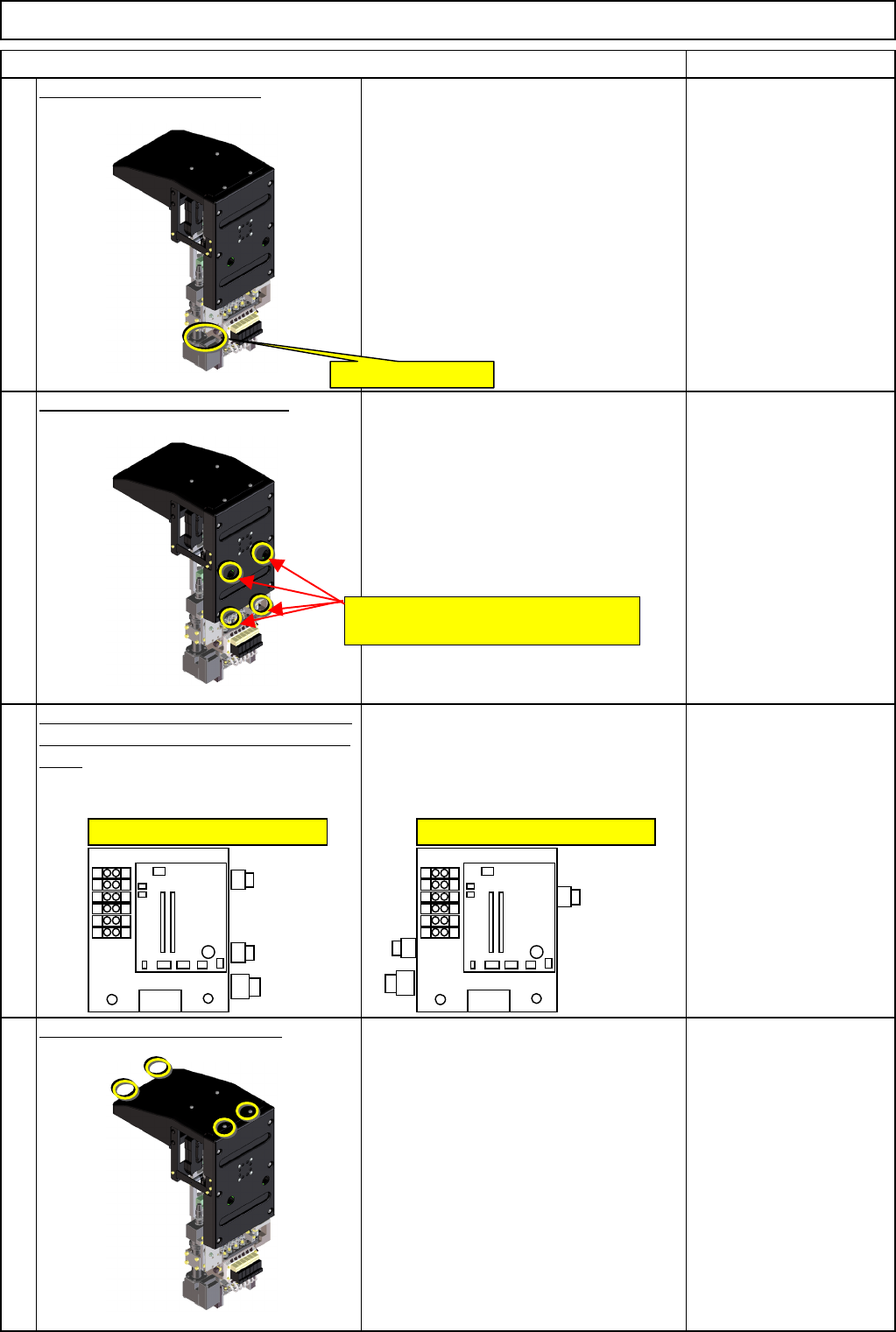
Remove the LED connector.
Remove the head-holding bolts.
Allen key 5 mm
Pipe
M6 screw 4 pcs.
After the screws have
been removed, hold the
head by hand.
(Otherwise, it can fall
down.)
Check the positions of the air tube joints
of the new head and the head-mounting
table.
* Positions of the joints when seen from
the operator's side:
AF and BR: Right
AR and BR: Left
Remove the upper head cover.
Phillips screwdriver #2
M4 truss 4 pcs.
13
14
15
16
LED light connector
Positions of AF and BR joints Positions of AR and BF joints
Insert an Allen key through these
positions into the head-holding bolts.
EJM8A-E-SMA051001-A01-00
Page 5-10-1-5
Machinery Part Replacement
Remark
Item
12-Nozzle Head Unit
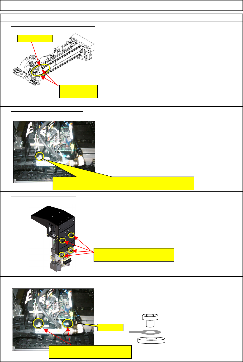
Mount the transfer head on the X beam.
• Check there are no dust or cuts on the
X-beam head plate.
• Mount the head, checking the
mounting guides on the head and the
plate sides.
• Check the dowel-pin hole on the head
side is aligned with the dowel-pin
position on the plate side.
• Check no cables are caught.
Provisionally fix the head in place.
• Hold the head by hand until the head
has been fixed provisionally.
• Put the bolts somewhere convenient so
that you can get them immediately when
you need them.
M4 x 8L
Thick washer
Tighten the head-holding bolts.
• Check the head makes a close contact
with the plate.
Allen key 5 mm
Pipe
M6 screw 4 pcs.
Tighten the earth section and the
provisionally holding bolt. • Tighten the upper provisionally holding
bolt.
• Put the earth terminal on the right, and
tighten it.
M4 x 8L 2 pcs.
Thick washer
19
17
18
20
Mounting guide
Head-positioning
dowel pins
Provisionally fix the head with the M4 x 8L screw and the thick
washer.
FG⇒Earth
Tighten them with the M4 x 8L screws
and the thick washers.
Insert an Allen key through these
positions into the head-holding bolts.
EJM8A-E-SMA051001-A01-00
Page 5-10-1-6