CM602all_EJM8AESM_Service Manual.pdf - 第610页
Machinery Part Replacement Remark Item 12-Nozzle Head Unit Connect the LED connector. Put the upper head cover back on. Phillips screwdriver #2 M4 truss 4 pcs. the front side. Remove the covers (large and small) f rom th…
Machinery Part Replacement
Remark
Item
12-Nozzle Head Unit
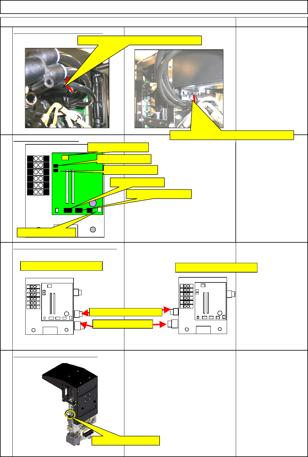
Secure the tubes with a cable tie.
Nippers
Connect the connectors.
Connect the tube joints and lock them.
Connect the camera connector.
22
23
24
21
Secure the AF and BR tubes with a cable tie.
Secure the AR and BF tubes with a cable tie.
C12-M(st,No)⇒CN12
C8-M(st,No)⇒CN8
C9-M(st,No)⇒CN9
C1-M(st,No)⇒CN1
CN11-M(st,No)⇒CN11
CN2-M(st,No)⇒CN2
Positions of AF and BR joints
Positions of AR and BF joints
Head camera connector
Vacuum joints
Vacuum release joints
EJM8A-E-SMA051001-A01-00
Page 5-10-1-7
Machinery Part Replacement
Remark
Item
12-Nozzle Head Unit
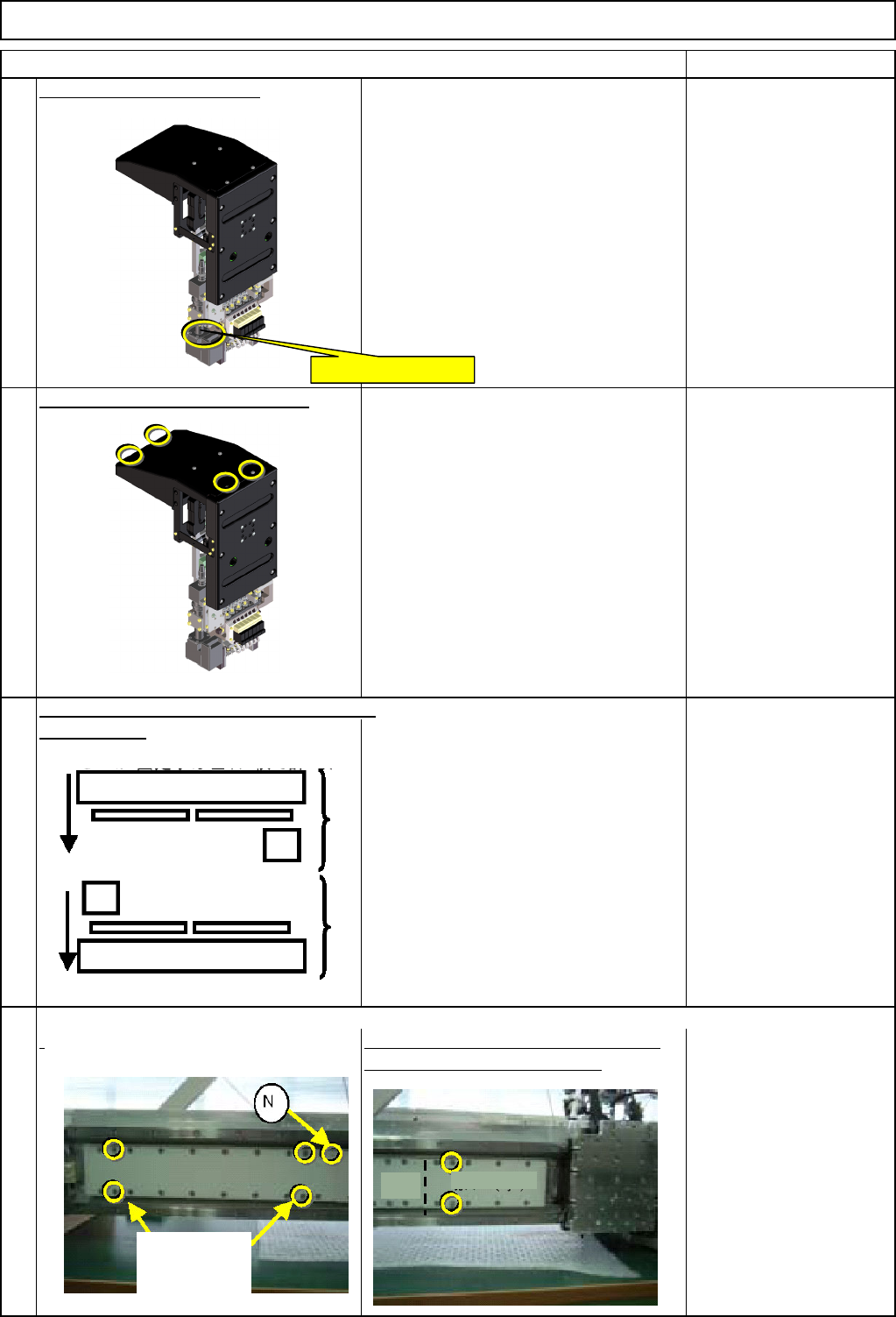
Connect the LED connector.
Put the upper head cover back on.
Phillips screwdriver #2
M4 truss 4 pcs.
the front side.
Remove the covers (large and small)
f
rom the secondary part. * Magnets are installed. Ensure safety
when working on the machine.
Cover (Large) Bolts x 4
Cover (Small) Bolts x 2
* Non-magnetic Allen
keys
Move the front and the rear beams towards
28
25
26
27
LED light connector
Rear
Front
(Large
)
Cover (Small)
Bolts
accompanying
the machine
EJM8A-E-SMA051001-A01-00
Page 5-10-1-8
Machinery Part Replacement
Remark
Item
12-Nozzle Head Unit
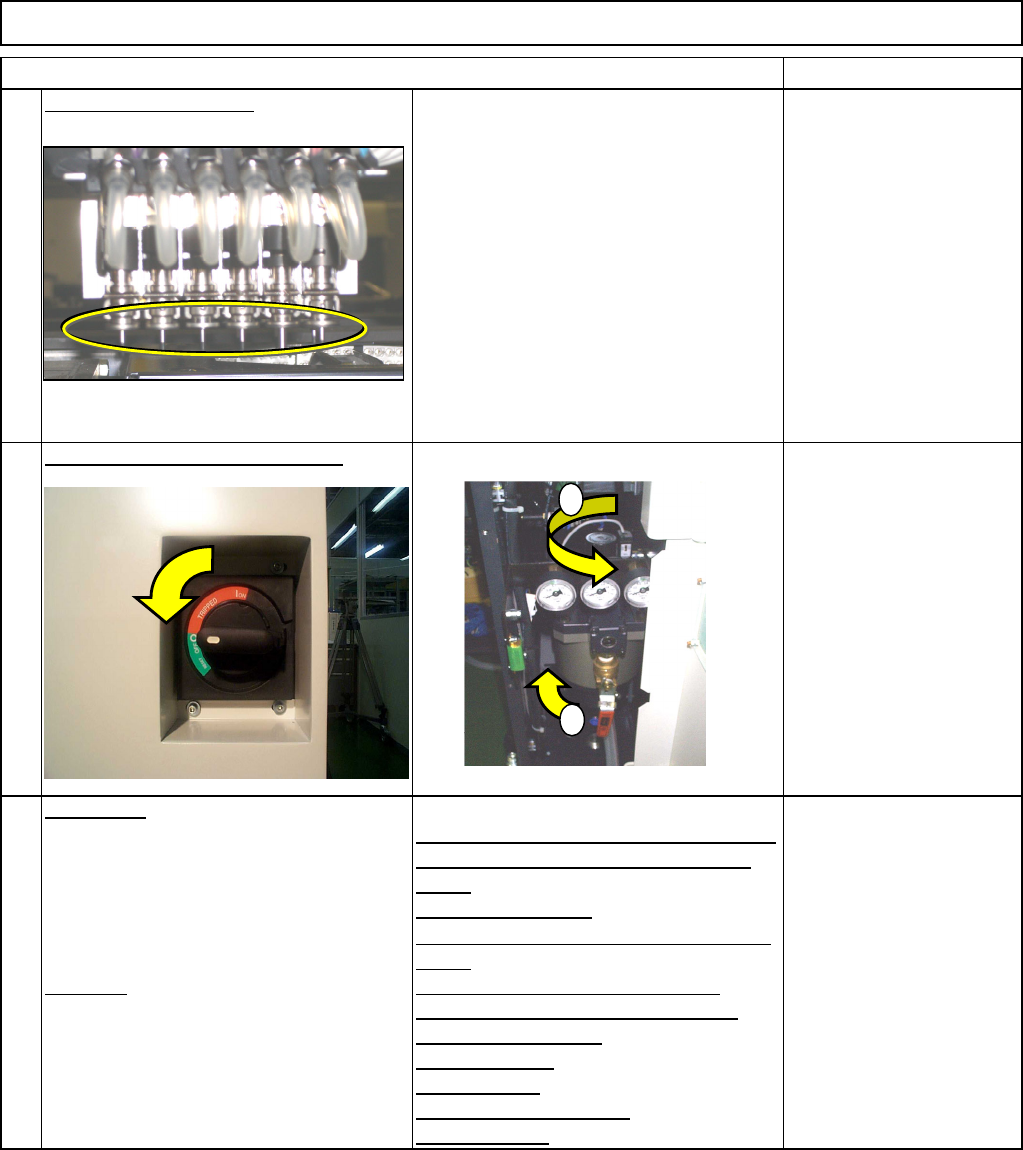
Put the nozzle back on.
Turn on the power and air supply.
Adjustment
Teaching
Head Camera Adjustment (Focus and q)
Board Recognition Camera XY Origin
Offset
Z-axis Origin Offset
Chip Recognition Camera, θ-axis Origin
Offset
Width Adjusting-axis Origin Offset
Mount Height and Board Positioning
XY Plane Calibration
Pickup Position
Light Intensity
Nozzle Change Position
Mount Position
Section 5-11-1
Section 5-11-2
Section 5-11-3
Section .5-11-4
Section 5-11-5
Section 5-11-6
Section 5-11-7
Section 5-11-8
Section 5-11-9
Section 5-11-10
Section 5-11-11
29
30
31
1
2
EJM8A-E-SMA051001-A01-00
Page 5-10-1-9