CM602all_EJM8AESM_Service Manual.pdf - 第614页
Machinery Part Replacement Remark 12-Nozzle Head Unit Item Remove the collar and the bearing from the s p line shaft. 7 Pull the spline shaft out of the bearing case. * To remove the bearing case, remove all the spline s…
Machinery Part Replacement
Remark
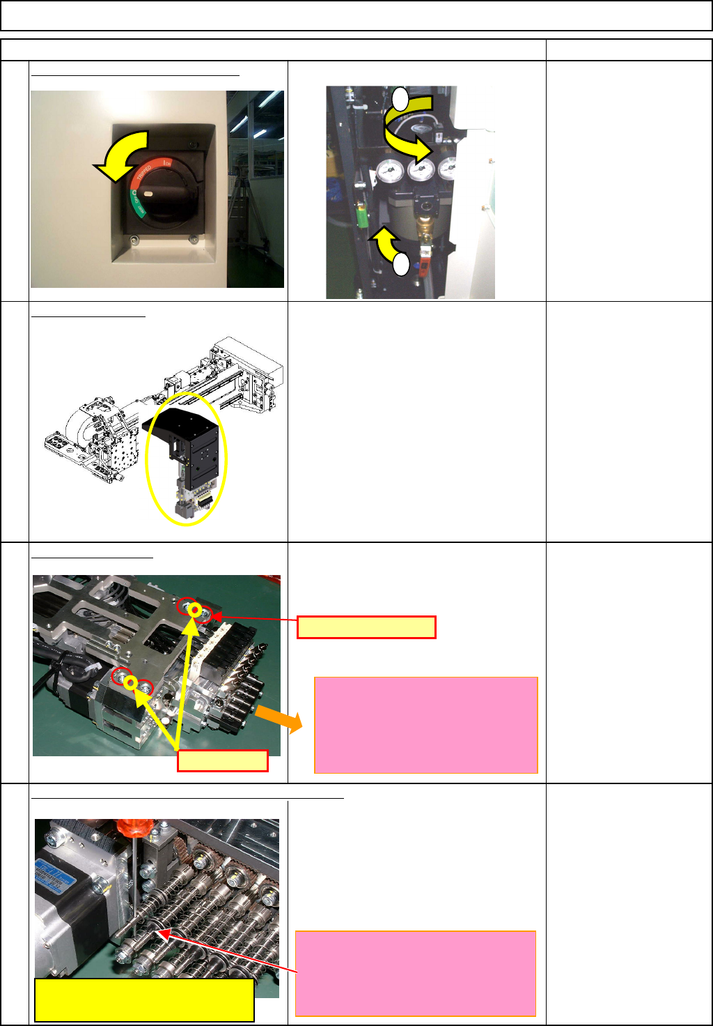
Turn off the power and air supply.
Remove the head.
See "12-Nozzle-Head-Unit
Replacement."
Section 5-10-1
Se
p
arate the θ-unit.
See "θ-Unit Removal."
Section 5-10-8
Be careful; the spring jumps out.
M3 nut
4
Remove the upper bearings from the spline shafts.
12-Nozzle Head Unit
1
2
3
Item
1
2
D-PIN
Pin position
M5 x 12L (4 pcs.)
Put the shaft through the axis so that
the spring is held cnotracted.
Be sure to use a rod.
Using an Allen key or an equivalent
tool may leave a dent on the end of
the spline-shaft hole.
The ball-spline shafts should be
extended so that the ends of the
shafts do not touch any other parts
when mounting the unit on the θ-
axis.
EJM8A-E-SMA051002-A01-00
Page 5-10-2-2
Machinery Part Replacement
Remark
12-Nozzle Head Unit
Item
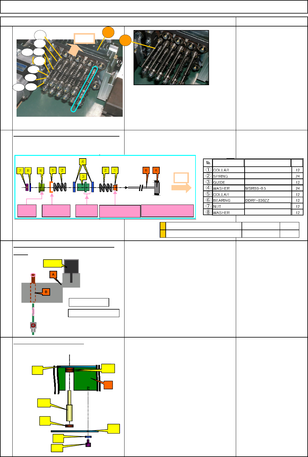
Remove the collar and the bearing from
the s
p
line shaft.
7
Pull the spline shaft out of the bearing
case. * To remove the bearing case, remove
all the spline shafts.
All the removed spline shafts but the one
to replace should be put back in the
bearing case later. Keep them in a safety
place.
8
Remove the bearing case.
• Loosen the four ③ (M3x6L) bolts, and
remove them. Remove the ⑥ plate.
• Remove the (1) bearing and the (5)
bearing case.
M3×6L
5
6
B
A
A
1
2
3
4
2
5
6
7
8
A
: Housing
B: Bearing case
①
(1)
(2)
(3)
(4)
(6)
(1)
(5)
A
Convex
side: A
Concave
side: A
Shorter:
A
Convex side:
Opposite to A
cegh:Be careful of
direction.
A
Part name Model Qty.
Hexagonal nut M3 Type 1
Flat small round washer M3
Ball spline (Spline shaft)
θ
-axis housing
A
B
* A assembled
*P001
(12)
1
Motor
EJM8A-E-SMA051002-A01-00
Page 5-10-2-3
Machinery Part Replacement
Remark
12-Nozzle Head Unit
Item
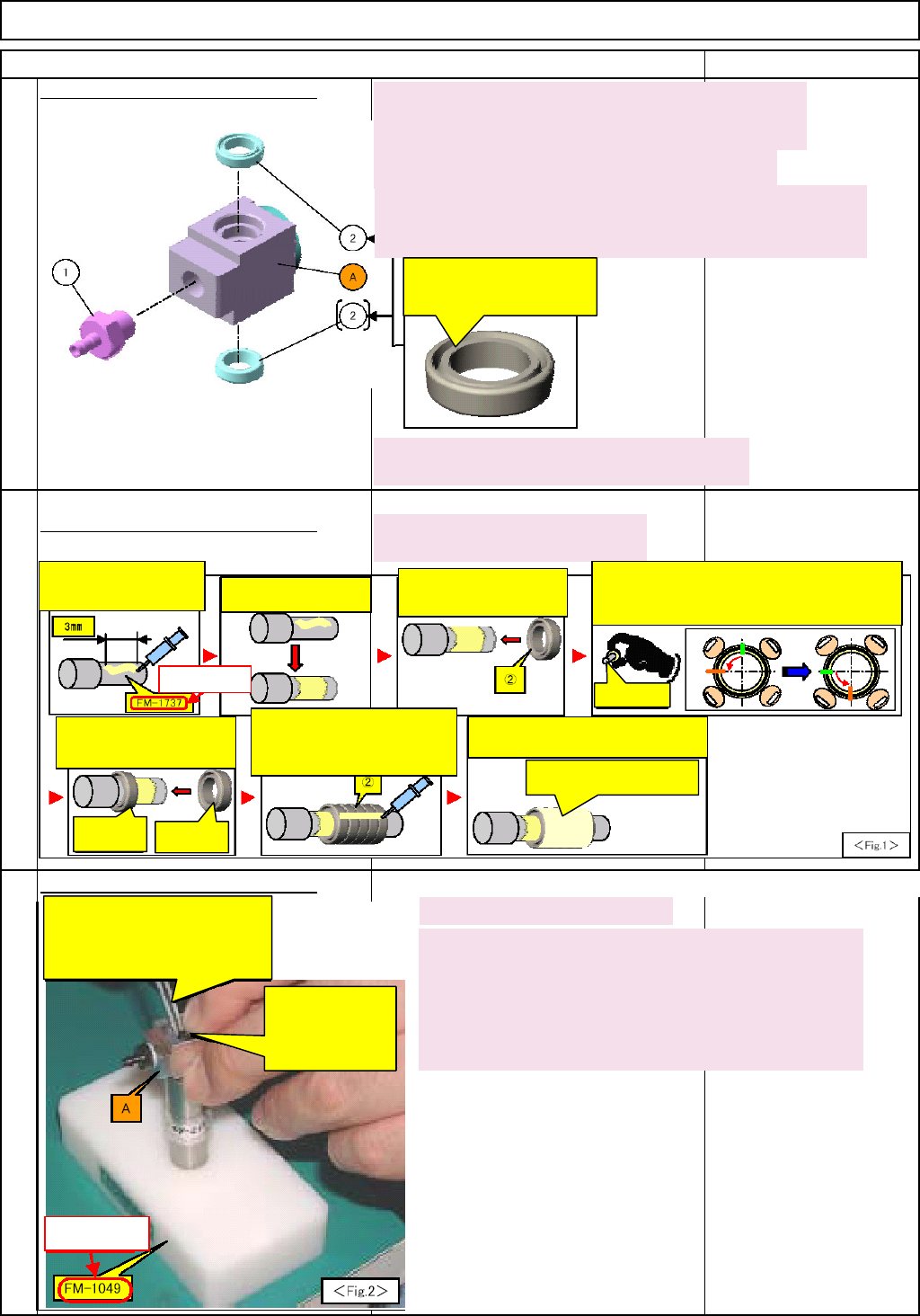
9
Fitting the joint and the packing (1)
10
Fitting the joint and the packing (2)
Barrierta
FM-1737
Fitting the joint and the packing (3)
FM-1049
11
1. Visually check the housing (A) for dirt and dust.
Check no cutting dust or dirt builds on the inside of the A
(especially tapping section) with a magnifier.
2. Preparation of Housing (A).
A
ir (A) to blow cutting dust and dirt away from the tube.
3. Check the Housing (A) preparation
Check with a magnifier that cutting dust and dirt have been away
from the inside of A (especially tapping section).
4. Fit (1) on the housing (A) at the specified torque.
Tightening torque: 3.3 N•m
The groove side should
be the outside of (A)
6. Put the housing (a) onto the jig.
7. Fit (2)s in the housing (A). (upper and lower sides)
Be careful of the insertion direction and damage of (2). See
at left.
* The tweezers to use should be groove-free and the end
should be rounded.
Insert (2) with tweezers.
Be careful not to damage (2).
(Tweezers to use should have no
groove and the end of the tweezers
should be rounded.)
(2): Be careful of
insertion direction and
damage. Insert it fully.
5. Apply grease to (2).
For greasing procedures, see below.
I. Apply grease to the 3-mm
area of the jig with an
injector
II. Spread the grease
slightly around the shaft.
III. Put (2) onto the jig with
the groove surface of (2)
facin
g
the
j
i
g
.
(
See above
)
IV. To spread the grease to all the groove, push (2)
with your fingers (with the jig kept inserted) and turn
(2) 90 degrees. Hold a 90-degree away position of (2)
and turn another 90 de
g
rees.
(2) + Jig
V. After greasing (2) has been
finished, leave (2) on the jig
and repeat steps I to IV.
VI. After several (2)s have been
greased, put them together, and
apply grease to the outside of the
(2)s.
VII. Spread the grease to the entire area
of (2)s with your finger. Remove (2)s.
Greased (2)
A
nother (2)
Spread the grease to the
entire area of (2)s.
Not decided yet.
Not decided yet.
EJM8A-E-SMA051002-A01-00
Page 5-10-2-4