CM602all_EJM8AESM_Service Manual.pdf - 第619页
Machinery Part Replacement Remark 12-Nozzle Head Unit Item A ssemble the θ - unit. 23 See " θ -unit Removal." Section 5-10-8 Mount the head assembly. 24 See "12-Nozzle Head-Unit Replacement." Section …
Machinery Part Replacement
Remark
12-Nozzle Head Unit
Item
Shaft insertion
(
2
)
19
Shaft insertion
(
3
)
20
A
ssemblin
g
the
p
eri
p
heral section
(
1
)
21
22
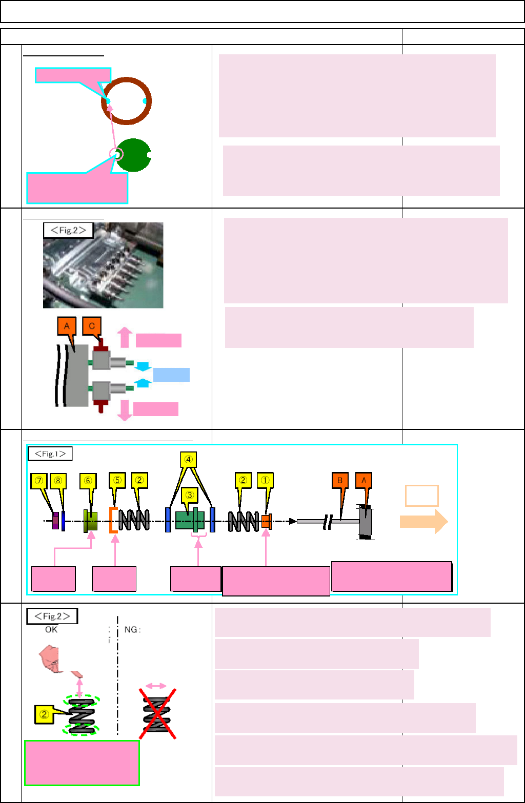
3. The shaft code of the spline housing (C) should face
outwards.
Make the code of (C) face outwards so that it faces in the
same direction as that of the bearing case (B).
4. Apply grease to the spline housing (C) slightly. The shaft
groove should be filled with grease. (See Figure 18.)
Bearing ball
A
lign it with the shaft
groove. Insert the shaft
into B.
5. Insert the bearing case (B) into the spline housing (C)
lightly.
Position the mouth of the joint (with C assembled)
outwards, and insert (B) into (C), aligning the bearing balls in
the (B) shaft with the groove of (C). Be careful no to let the
bearing ball jump out.
6. Repeat Steps 1 to 4 until the total of twelve (12)
kits are created.
Outwards
Inwards
Apply grease to the
both ends of the spring
(2).
1. Insert the spline shaft (B) (with A assembled) through (1)
Be careful of the direction of (1).
2 . Apply grease to both ends of (2) slightly.
The total of 24
3. Insert the spline shaft (B) through (2).
Insert B into greased (2). The total of 12
A
pply grease to
the upper and
lower surfaces
of the spring.
Spread the
grease
horizontally.
4. Insert the spline shaft (B) through (3) and (4).
(3) should be between (4)s. Check the direction of (3).
5. Insert the spline shaft (B) through (2) and (5).
Insert B through greased (2) and (5). Check the direction of (5).
6. Join (6) to the kit above (in Step 5) with (7) and (8).
Assembling torque : 108 +/-9 N•cm. Check the direction of (6).
Convex
side: A
Concave
side: A
Shorter: A Convex side: Opposite of
A
* Be careful of direction
of cegh
A
Outwards
EJM8A-E-SMA051002-A01-00
Page 5-10-2-7
Machinery Part Replacement
Remark
12-Nozzle Head Unit
Item
A
ssemble the
θ
- unit.
23
See "θ -unit Removal."
Section 5-10-8
Mount the head assembly.
24
See "12-Nozzle Head-Unit
Replacement."
Section 5-10-1
Turn on the power and air supply.
25
A
d
j
ustment
Teaching
Head Camera Adjustment (Focus and θ)
Board Recognition Camera XY Origin
Offset
Z-axis Origin Offset
Chip Recognition Camera, θ-axis Origin
Offset
Width Adjusting-axis Origin Offset
Mount Height and Board Positioning
XY Plane Calibration
Pickup Position
Light Intensity
Nozzle Change Position
Mount Position
Section 5-11-1
Section 5-11-2
Section 5-11-3
Section .5-11-4
Section 5-11-5
Section 5-11-6
Section 5-11-7
Section 5-11-8
Section 5-11-9
Section 5-11-10
Section 5-11-11
26
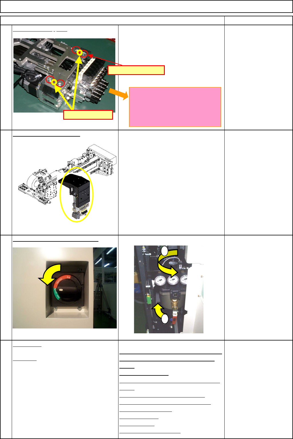
Pin positions
M5 x 12L (4 pcs.)
1
2
The ball-spline shafts should be
extended so that the ends of the
shafts do not touch any other parts
when mounting the unit on the θ-
axis.
EJM8A-E-SMA051002-A01-00
Page 5-10-2-8
Machinery Part Replacement
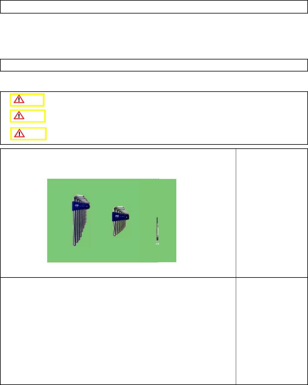
This section describes the procedures for replacing the vacuum-switching valve
Tools
Allen key
Precision screwdriver
Phillips screwdriver #2
Jig
None
5-10-3 Vacuum-Switching-Valve Replacement
12-Nozzle Head Unit
Caution
Dange
r
Warning
EJM8A-E-SMA051003-A01-00
Page 5-10-3-1