CM602all_EJM8AESM_Service Manual.pdf - 第620页
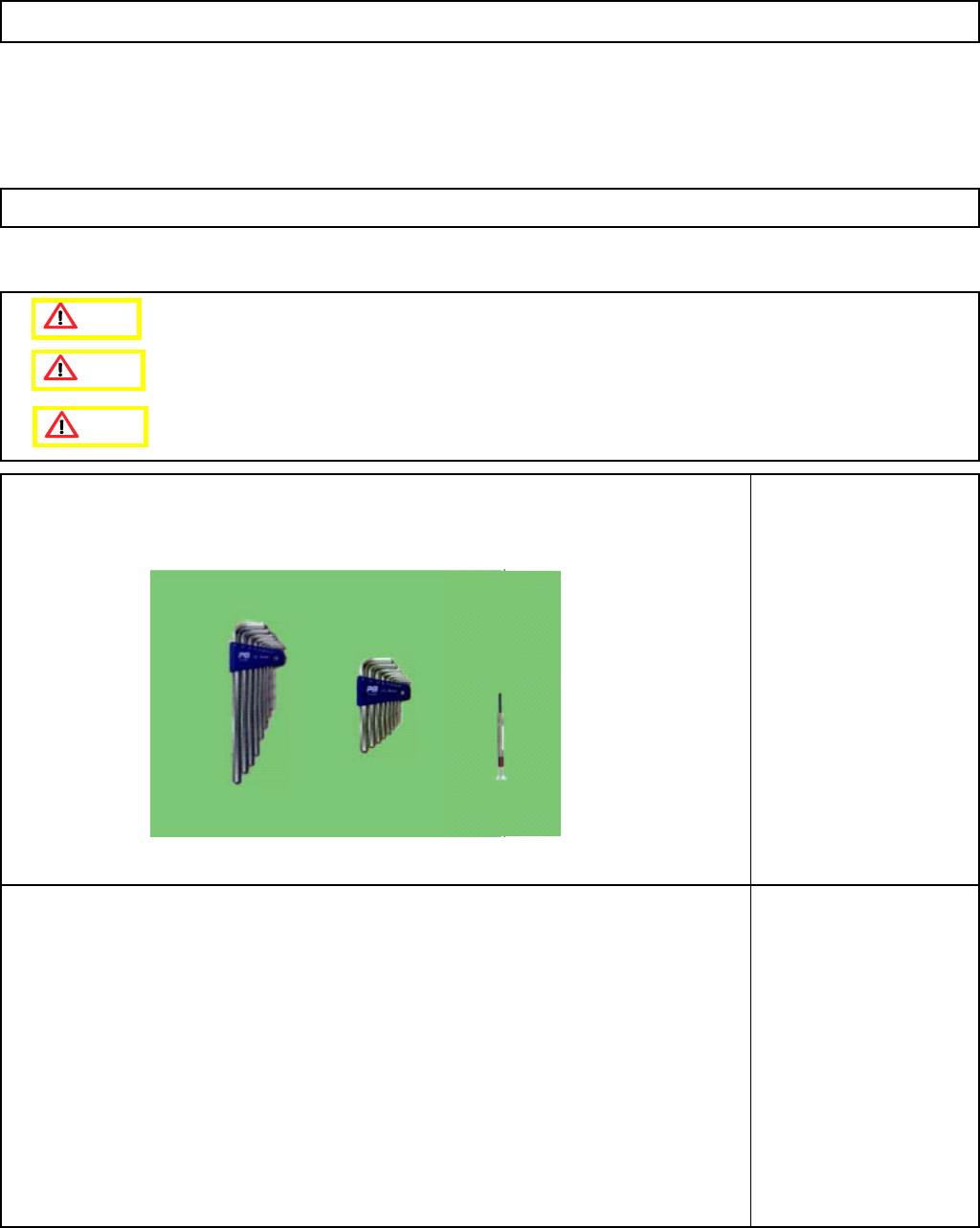
Machinery Part Replacement This section describes the procedures for replacing the vacuum-switching valve Tools Allen key Precision screwdriver Phillips screwdriver #2 Jig None 5-10-3 Vacuum-Switching-Valve Replacement 1…
Machinery Part Replacement
Remark
12-Nozzle Head Unit
Item
A
ssemble the
θ
- unit.
23
See "θ -unit Removal."
Section 5-10-8
Mount the head assembly.
24
See "12-Nozzle Head-Unit
Replacement."
Section 5-10-1
Turn on the power and air supply.
25
A
d
j
ustment
Teaching
Head Camera Adjustment (Focus and θ)
Board Recognition Camera XY Origin
Offset
Z-axis Origin Offset
Chip Recognition Camera, θ-axis Origin
Offset
Width Adjusting-axis Origin Offset
Mount Height and Board Positioning
XY Plane Calibration
Pickup Position
Light Intensity
Nozzle Change Position
Mount Position
Section 5-11-1
Section 5-11-2
Section 5-11-3
Section .5-11-4
Section 5-11-5
Section 5-11-6
Section 5-11-7
Section 5-11-8
Section 5-11-9
Section 5-11-10
Section 5-11-11
26
Pin positions
M5 x 12L (4 pcs.)
1
2
The ball-spline shafts should be
extended so that the ends of the
shafts do not touch any other parts
when mounting the unit on the θ-
axis.
EJM8A-E-SMA051002-A01-00
Page 5-10-2-8
Machinery Part Replacement
This section describes the procedures for replacing the vacuum-switching valve
Tools
Allen key
Precision screwdriver
Phillips screwdriver #2
Jig
None
5-10-3 Vacuum-Switching-Valve Replacement
12-Nozzle Head Unit
Caution
Dange
r
Warning
EJM8A-E-SMA051003-A01-00
Page 5-10-3-1
Machinery Part Replacement
Remark
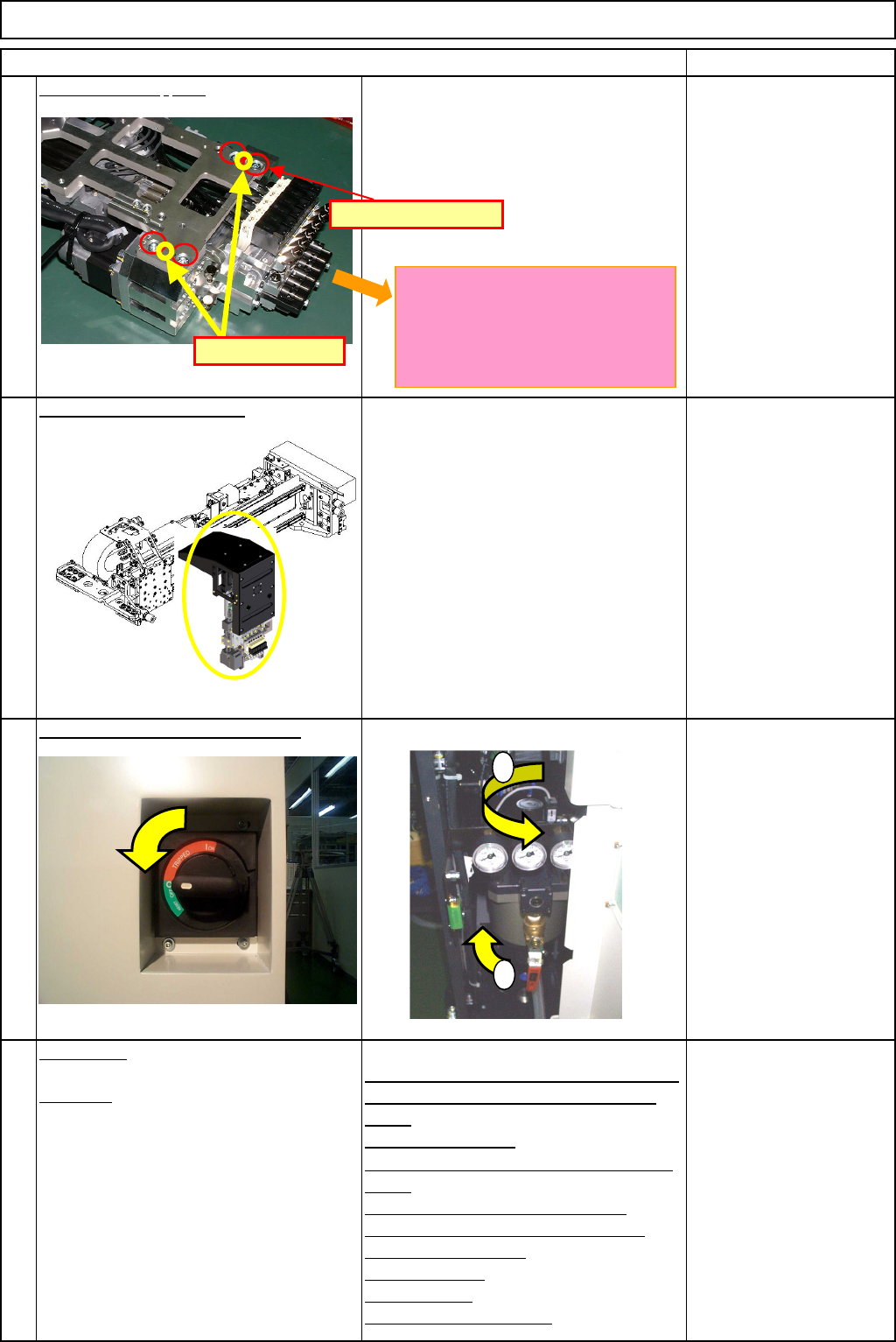
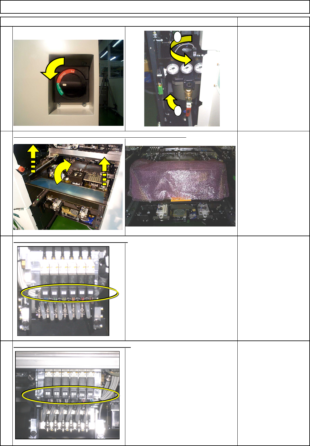
Turn off the power and air supply.
Phillips screwdriver #2
Bubble wrap
M4 screw 2 pcs.
Remove the valve connectors. (FWD side)
Air valve unit
* NP1 - 6 (A001)
Remove the valve connectors. (REAR side)
Air valve unit
* NP7 - 12 (A002)
3
4
1
Item
2
12-Nozzle Head Unit
Remove the feeder cover. Put bubble wrap over the body frame.
1
2
EJM8A-E-SMA051003-A01-00
Page 5-10-3-2