CM602all_EJM8AESM_Service Manual.pdf - 第629页
Machinery Part Replacement Remark Item 12-Nozzle Head Unit Removal of the p late ( B ) from the θ -axis housin g ( 1 ) 1-000319 Before removing the plate (B), loosen the hollowset (C). Hexagonal socket setscrew M4 x 4L 2…
Machinery Part Replacement
Remark
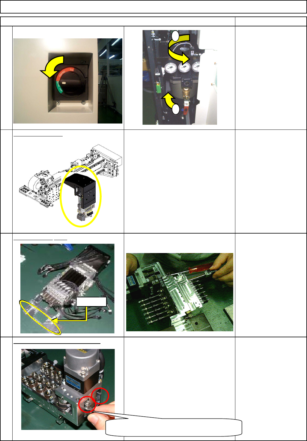
Turn off the power and air supply.
カバー達
0.49MPa to
0.55MPa
Remove the head.
See "12-Nozzle-Head-Unit
Replacement."
Section 5-10-1
Se
p
arate the
θ
-unit.
See "θ-Unit Removal."
Section 5-10-8
Remove the short belt tensioner.
1-000314
Allen key 3 mm
M3 x 12L 2 pcs.
Item
2
3
1
12-Nozzle Head Unit
4
1
2
The adjuster-holding bolt is under the adjuster.
One bolt for each adjuser
Dowel pin
EJM8A-E-SMA051005-A01-00
Page 5-10-5-2
Machinery Part Replacement
Remark
Item
12-Nozzle Head Unit
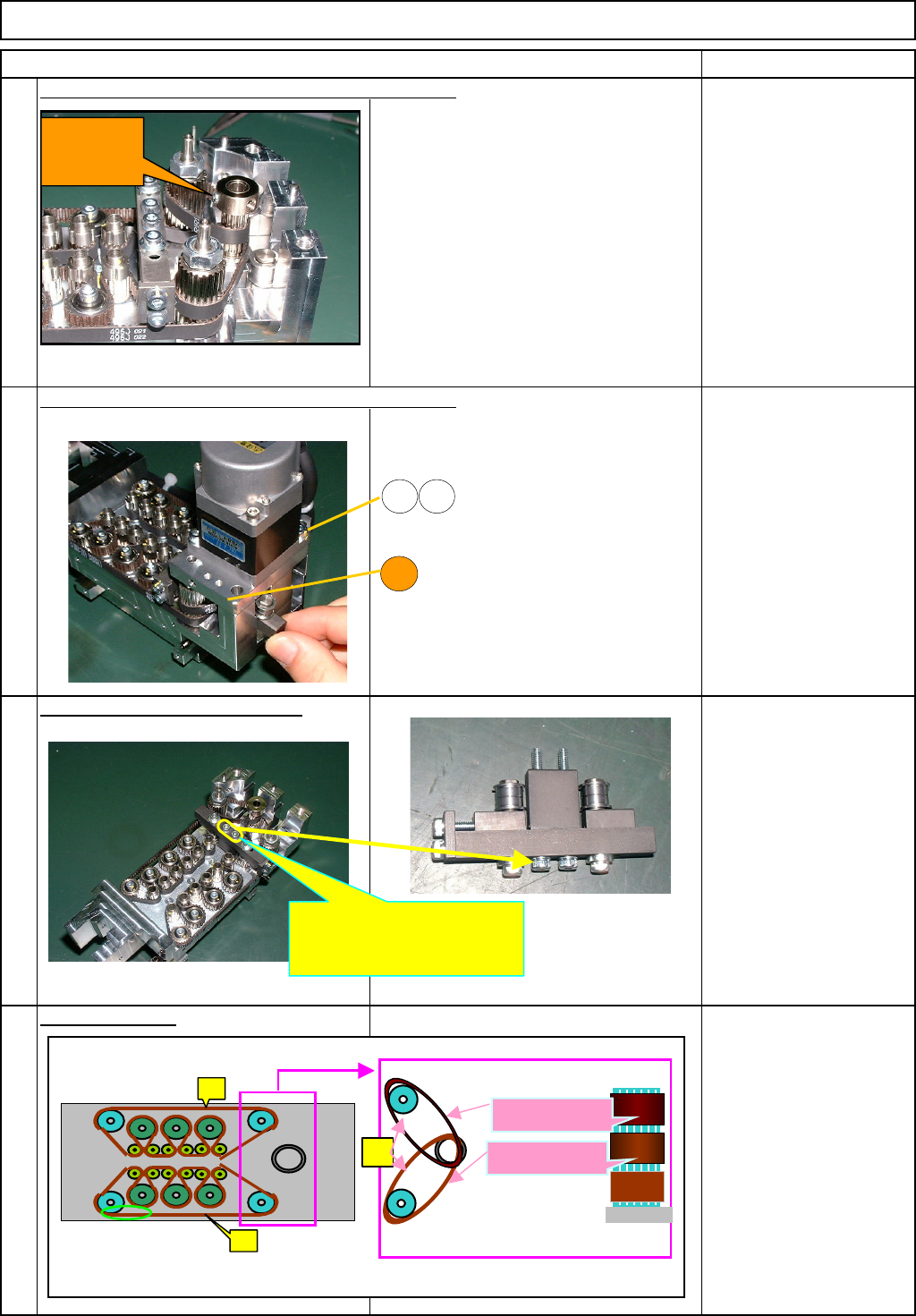
Removal of the
p
late
(
B
)
from the θ -axis housin
g
(
1
)
1-000319
Before removing the plate (B), loosen the
hollowset (C). Hexagonal socket
setscrew M4 x 4L
2 pcs.
Removal of the
p
late
(
B
)
from the θ -axis housin
g
(
2
)
Remove the M5 x 16L bolts (1) and (2),
and the M5 washer. M5×16L 2 pcs.
Remove the tension adjuster (B).
M3×35L 2 pcs.
Remove the belt.
Remove the belts (1), (2) and (3).
7
5
6
8
1 2
B
Loosen the
hollowset
(C).
Loosen these bolts and remove
the tension adjuster (B).
(1)
(2)
(3)
Assembly procedures 2
(Upper level)
A
ssembly procedures 1
(Middle level)
EJM8A-E-SMA051005-A01-00
Page 5-10-5-3
Machinery Part Replacement
Remark
Item
12-Nozzle Head Unit
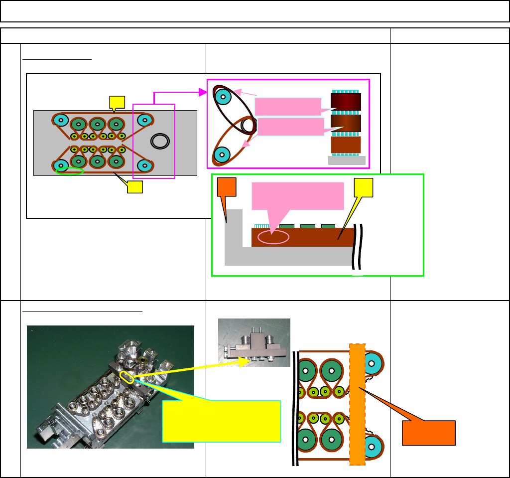
Install the belts.
Install the long belts (1) and (2), and two
s
h
o
r
t
be
l
ts
(3)
.
1-000319
Fit the tension adjuster (B).
1-000314
M3×35L 2 pcs.
9
10
(
1
(
2
Assembly procedures 2
(Upper level)
A
ssembly procedures 1
(Middle level)
AB
(3)
A
* The letters should
not be upside down.
Secure the tension adjuster
(B) with these bolts.
Bearing
EJM8A-E-SMA051005-A01-00
Page 5-10-5-4