CM602all_EJM8AESM_Service Manual.pdf - 第632页
Machinery Part Replacement Remark Item 12-Nozzle Head Unit Mount the p late ( B ) on the θ -axis housin g . 12 1. Mount the plate (B) on the θ -axis housing (A). Make the D-shaped cut of the motor shaft face the hollowse…
Machinery Part Replacement
Remark
Item
12-Nozzle Head Unit
Adjust the tension of the long belts.
11
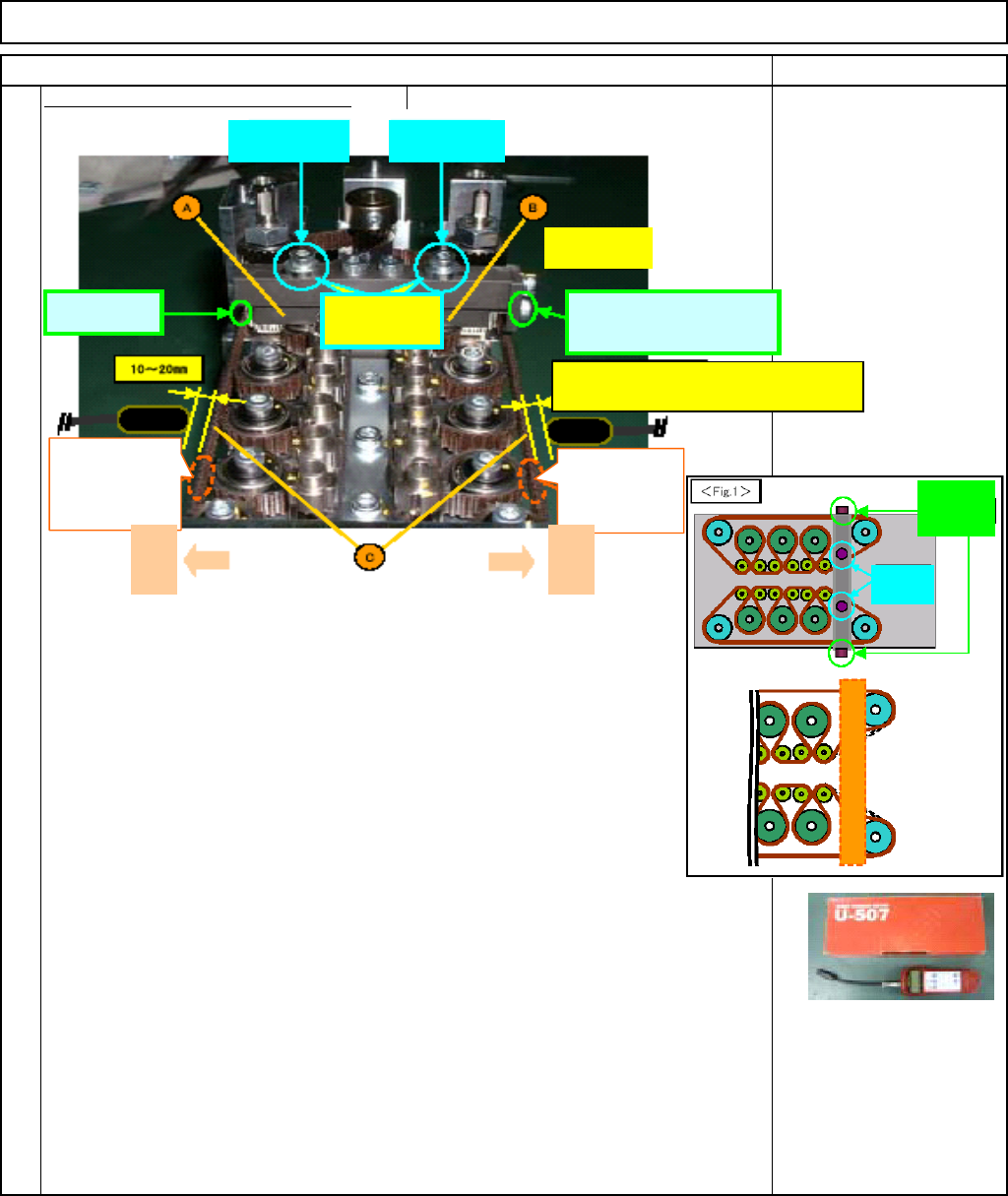
How to adjust the tension of the (long) belts (Two belts (Front and Rear))
1. Loosen the tension-adjuster-holding bolt.
2. Set the value of a ultrasonic measuring device. Prepare for measurement.
3. Put the measuring device close to the belt, and beat the belt. According
to the reading of the measuring device, adjust the belt tension with the
adjusting bolt.
Put a measuring device close to the belt (right angle against the belt,
10 - 20 mm away). Beat it with a ball-point wrench or similar tool that
does not damage the belt, and measure the tension.
* Tension should be 16N +/- 2N.
4. Re-adjust the tension after rotating the θ-motor manually.
Rotate the θ-axis motor manually (Rule: One rotation of the belt with
a 2-mm wrench), and beat the belt again. Adjust the tension if necessary.
5. Tighten the tension-adjuster-holding bolt.
6. To check the tension, re-measure it.
To check tightening the holding bolt did not change the tension, re-measure the tension
7. Repeat the procedures for the rear belt.
Rear holding
belt
Front holding
belt
Rear adjusting
bolt
Provisionally
tighten these
bolts
Provisionally
tighten this bolt
Beat the belt with
some tool that
does not damage
the belt.
Front adjusting bolt
(Used for tension
ad
j
ustment
)
Put a measuring device 10 - 20 mm approx. away
from the belt, and measure the tension.
Beat the belt with
some tool that
does not damage
the belt.
Front
For
adjusting
For
holding
Rear
EJM8A-E-SMA051005-A01-00
Page 5-10-5-5
Machinery Part Replacement
Remark
Item
12-Nozzle Head Unit
Mount the
p
late
(
B
)
on the θ-axis housin
g
.
12
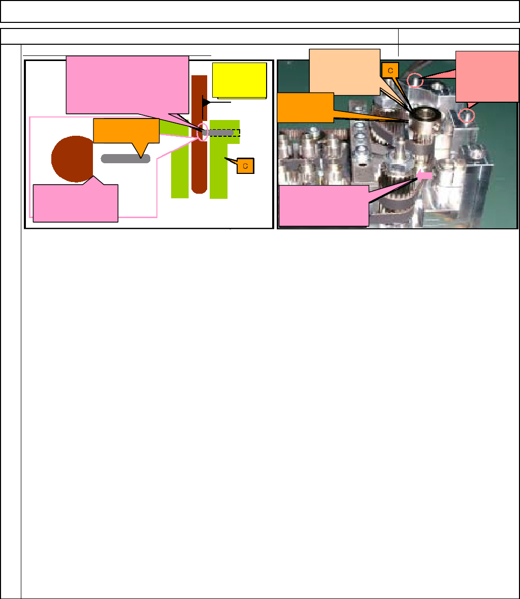
1. Mount the plate (B) on the θ-axis housing (A).
Make the D-shaped cut of the motor shaft face the hollowset (coupled with the pulley C).
Insert the dowel pins (coupled with A) into the holes of B.
2. Fix the pulley (C) and the motor shaft with the hollowset (coupled with C).
Fix the hollowset onto the D-shaped cut of the motor shaft. Press down C to avoid letting C rise.
3. Centering of the motor
If the pulley (C) does not rotate smoothly, center the motor. (Ex. Loosen the bolts that fix the motor
onto the plate (B).)
4. Fit the tension adjuster C (D) onto the θ-axis housing (A) with (3) and (4).
Pressing D against the timing belt, fix it onto A with (3) and (4).
5. Fit the tension adjuster B (E) onto the θ-axis housing (A) with (3) and (4).
Pressing E against the timing belt, fix it onto A with (3) and (4).
6. Adjust the tension of the timing belts by controlling the tension adjusters (D, E, and F).
Great care must be taken for the surrounding of each pulley when adjusting the tension.
Pressing the end of the
hollowset against the D-
shaped cut, fix the shaft and
the pulley (C) in place.
The D-shaped cut
should face the
hollowset.
ホロセット
:C組み付け
済
D-shaped cut
of the motor
shaft
Should NOT be
raised when
fixed.
Insert these
dowel pins into
the holes of the
plate (B).
Press D against the
timing belt and adjust
the tension.
Hollowset:
coupled with C
Hollowset:
coupled with C
EJM8A-E-SMA051005-A01-00
Page 5-10-5-6
Machinery Part Replacement
Remark
Item
12-Nozzle Head Unit
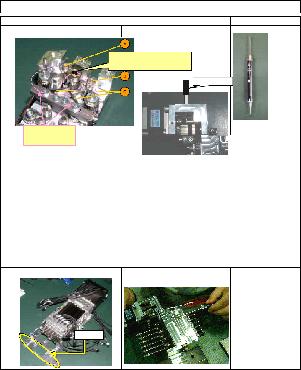
Adjust the tension of the short belt.
Install the θ-unit.
14
See "θ-Unit Removal."
Section 5-10-8
13
A
djust the tension o
f
the two belts.
This pulley should be connected
with the θ-axis motor.
Tension gauge
How to adjust the tension of the short belt (two belts)
1. Loosen the tension-adjuster-holding bolt.
Loosen the bolt for the section to be adjusted. Do not loosen the two bolts at the same time.
2. With 18.5 +/- 1.5N-pressure applied to one belt with tension gauge, rotate the θ-axis motor five
turns manually, and tighten the tension-adjuster-holding bolt.
With 10-N tension applied to the belt, fix the tension adjuster.
However, to release the excessive tension applied, rotate the θ-axis motor approximately five turns.
3. Repeat the procedures for the other belt.
Dowel pin
EJM8A-E-SMA051005-A01-00
Page 5-10-5-7